Deserializer1D
Convert scalar stream or smaller vectors to vector signal
Library
HDL Coder / HDL Operations

Description
The Deserializer1D block buffers a faster, scalar stream or vector signals into a larger, slower vector signal. The faster input signal is converted to a slower signal based on the Ratio and Idle Cycle values, the conversion changes sample time. Also, the output signal is delayed one slow signal cycle because the serialized data needs to be collected before it can be output as a vector. See the examples below for more details.
You can configure the deserialization to depend on a valid input signal ValidIn and a start signal StartIn. If the ValidIn and StartIn block parameters are both selected, data collection starts only if both ValidIn and StartIn signals are true. Consider this example:

Ratio is
2and Idle Cycles is0, so each output cycle is two input signals long with all data points considered.ValidIn and StartIn are selected, so data collection can begin only when both StartIn and ValidIn signals are true.
ValidOut is selected.
In the first cycle, ValidIn and StartIn are true, so data collection begins for A and B. The block outputs the deserialized vector in the next valid cycle, so the AB vector is output in the next cycle. This is also true in the second cycle for C and D.
In the third cycle, starting at E, StartIn is true, but ValidIn is not. E is dropped. At F, ValidIn is true, but StartIn is not, so F is also dropped. Since it cannot collect data for E or F, Deserializer1D outputs the previous cycle vector, CD, but ValidOut changes to false.
Another scenario to consider is when the StartIn signal arrives too early. If the length between two StartIn signals is not long enough to collect a full ratio cycle, the insufficient signal data is dropped. Consider this example:
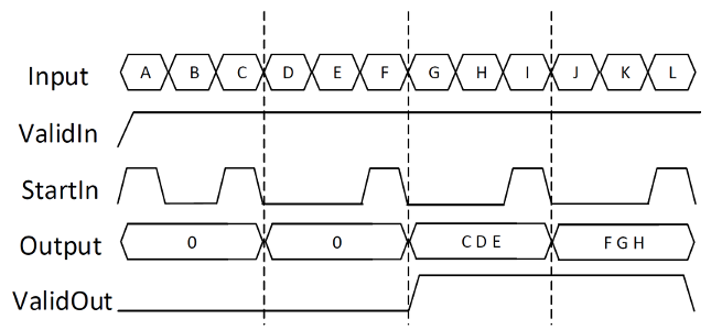
Ratio is
3, so each cycle is two sections long.Idle Cycles is
0, so all data inputs are considered.ValidIn and StartIn are selected, so data collection can begin only when both StartIn and ValidIn signals are true.
ValidOut is selected.
In the first cycle, ValidIn and StartIn are true, so data collection can begin for A and B. However, at C another StartIn signal arrives before three signals can be collected. Because the StartIn arrived early, A and B are dropped and no valid vector is collected during the first cycle. Therefore, the output of the second cycle is still zero. Deserialization begins at the StartIn at C, for C, D, and E. This vector is output at the next valid cycle, which is cycle 3. Similarly, deserialization starts again at the StartIn at F, and outputs the FGH vector in the fourth cycle.
You specify the block output for the first sampling period with the value of the Initial condition parameter.
Parameters
- Ratio
Enter the deserialization ratio. Default is
1.The ratio is the output vector size, divided by the input vector size. The ratio must be divisible by the input vector size.
- Idle Cycles
Enter the number of idle cycles added to the end of each serialized input. Default is
0.The value of Idle Cycles affects the deserialized output rate. For example, if Ratio is
2and the input signal isA, B, B, C, D, D, ..., without idle cycles the output would beAB, BC, DD.... However for the same input and ratio with Idle Cycles set to1, the output isAB, CD.... The idle cycles,BandD, are dropped.The Deserializer1D behavior changes if Idle Cycles is not zero, and ValidIn or StartIn are on. The idle cycles value affects only the output rate, while ValidIn and StartIn control what input data is deserialized.
- Initial condition
Specify the initial output of the simulation. Default is 0.
- StartIn
Select to activate the StartIn port. Default is off.
- ValidIn
Select to activate the ValidIn port. Default is off.
- ValidOut
Select to activate ValidOut port. Default is off.
- Input data port dimensions (-1 for inherited)
Enter the size of the input data signal. The input size must be divisible by the ratio plus the number of idle cycles. By default, the block inherits size based on context within the model.
- Input sample time (-1 for inherited)
Enter the time interval between sample time hits or specify another appropriate sample time such as continuous. By default, the block inherits its sample time based on context within the model. For more information, see Sample Time.
- Input signal type
Specify the input signal type of the block as
auto,real, orcomplex.
Ports
SInput signal to deserialize. Bus data types are not supported.
ValidInIndicates valid input signal. Use with the Serializer1D block. This port is available when you select the ValidIn check box.
Data type: Boolean
StartOutIndicates where to start deserialization. Use with the Serializer1D block. This port is available when you select the StartOut check box.
Data type: Boolean
PDeserialized output signal. Bus data types are not supported.
ValidOutIndicates valid output signal. This port is available when you select the ValidOut check box.
Data type: Boolean