Minimum
Minimum values of input or sequence of inputs
- Library:
DSP System Toolbox / Statistics
DSP System Toolbox HDL Support / Statistics
Description
The Minimum block identifies the value and position of the smallest element in each row or column of the input, or along vectors of a specified dimension of the input. It can also compute the minimum value of the entire input. The Minimum block can also track the minimum values in a sequence of inputs over a period of time. The Mode parameter specifies the block's mode of operation and can be set to one of the following:
Value— The block outputs the minimum values in the specified dimension.Index— The block outputs the index array of the minimum values in the specified dimension.Value and Index— The block outputs the minimum values and the corresponding index array in the specified dimension.Running— The block tracks the minimum values in a sequence of inputs over a period of time.
You can specify the dimension using the Find the minimum value over parameter.
Note
The Running mode in the Minimum block will be removed in a future release. To compute the running minimum in Simulink®, use the Moving Minimum block instead.
Ports
Input
Output
Parameters
Main Tab
Mode — Mode in which the block operates
Value and Index (default) | Value | Index | Running
When the Mode parameter is set to:
Value— The block computes the minimum value in each row or column of the input, along vectors of a specified dimension of the input, or of the entire input at each sample time, and outputs the array y. Each element in y is the minimum value in the corresponding column, row, vector, or entire input. The output y depends on the setting of the Find the minimum value over parameter. Consider a three dimensional input signal of size M-by-N-by-P. Set Find the minimum value over to:Each row— The output y at each sample time consists of an M-by-1-by-P array, where each element contains the minimum value of each vector over the second dimension of the input. For an input that is an M-by-N matrix, the output at each sample time is an M-by-1 column vector.Each column— The output y at each sample time consists of a 1-by-N-by-P array, where each element contains the minimum value of each vector over the first dimension of the input. For an input that is an M-by-N matrix, the output at each sample time is a 1-by-N row vector.In this mode, the block treats length-M unoriented vector inputs as M-by-1 column vectors.
Entire input— The output y at each sample time is a scalar that contains the minimum value in the M-by-N-by-P input matrix.Specified dimension— The output y at each sample time depends on Dimension. If Dimension is set to1, the output is the same as when you selectEach column. If Dimension is set to2, the output is the same as when you selectEach row. If Dimension is set to3, the output at each sample time is an M-by-N matrix containing the minimum value of each vector over the third dimension of the input.
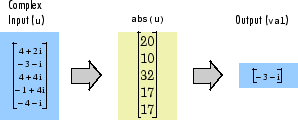
Complex Inputs
For complex inputs, the block selects the value in each row or column of the input, along vectors of a specified dimension of the input, or of the entire input that has the minimum magnitude squared in the following figure. For complex value , the magnitude squared is .
Index— The block computes the minimum value in each row or column of the input, along vectors of a specified dimension of the input, or of the entire input, and outputs the index array I. Each element in I is an integer indexing the minimum value in the corresponding column, row, vector, or entire input. The output I depends on the setting of the Find the minimum value over parameter. Consider a three dimensional input signal of size M-by-N-by-P:Each row— The output I at each sample time consists of an M-by-1-by-P array, where each element contains the index of the minimum value of each vector over the second dimension of the input. For an input that is an M-by-N matrix, the output at each sample time is an M-by-1 column vector.Each column— The output I at each sample time consists of a 1-by-N-by-P array, where each element contains the index of the minimum value of each vector over the first dimension of the input. For an input that is an M-by-N matrix, the output at each sample time is a 1-by-N row vector.In this mode, the block treats length-M unoriented vector inputs as M-by-1 column vectors.
Entire input— The output I at each sample time is a 1-by-3 vector that contains the location of the minimum value in the M-by-N-by-P input matrix. For an input that is an M-by-N matrix, the output is a 1-by-2 vector.Specified dimension— The output I at each sample time depends on Dimension. If Dimension is set to 1, the output is the same as when you selectEach column. If Dimension is set to 2, the output is the same as when you selectEach row. If Dimension is set to 3, the output at each sample time is an M-by-N matrix containing the indices of the minimum values of each vector over the third dimension of the input.
When a minimum value occurs more than once, the computed index corresponds to the first occurrence. For example, when the input is the column vector
[3 2 1 2 3]', the computed one-based index of the minimum value is1, rather than5whenEach columnis selected.Value and Index— The block outputs the minimum value in each row or column of the input, along vectors of a specified dimension of the input, or of the entire input, and the corresponding index array I.Running— The block tracks the minimum value of each channel in a time sequence of M-by-N inputs. The block resets the running minimum whenever a reset event is detected at the optionalRstport. The reset sample time must be a positive integer multiple of the input sample time. In this mode, you must also specify the Input processing parameter as one of the following:Elements as channels (sample based)— The block treats each element of the input as a separate channel. For a three-dimensional input signal of size M-by-N-by-P, the block outputs an M-by-N-by-P array. Each yijk element of the output contains the minimum value observed in element uijk for all inputs since the last reset.When a reset event occurs, the running minimum yijk in the current frame is reset to the element uijk.
Columns as channels (frame based)— The block treats each column of the input as a separate channel. This option does not support an N-dimensional input signal, where N > 2. For a two-dimensional input signal of size M-by-N, the block outputs an M-by-N matrix. Each element yij of the output contains the minimum value observed in the jth column of all inputs since the last reset, up to and including element uij of the current input.When a reset event occurs, the running minimum for each channel becomes the minimum value of all the samples in the current input frame, up to and including the current input sample.
The block resets the running minimum whenever a reset event is detected at the optional Rst port. The reset sample time must be a positive integer multiple of the input sample time.
Running Mode for Variable-Size Inputs
When the input is a variable-size signal, and you set the Mode to
Running, then:If you set the Input processing parameter to
Elements as channels (sample based), the state is reset.If you set the Input processing parameter to
Columns as channels (frame based), then:When the input size difference is in the number of channels (columns), the state is reset.
When the input size difference is in the length of channels (rows), there is no reset and the running operation is carried out as usual.
Index base — Base of the minimum value index
One (default) | Zero
Specify whether the index of the minimum value is reported using one-based or zero-based numbering.
Dependencies
To enable this parameter, set Mode to either
Index or Value and
Index.
Find the minimum value over — Dimension over which the block computes the minimum value
Each column (default) | Each row | Entire input | Specified dimension
Each column— The block outputs the minimum value over each column.Each row— The block outputs the minimum value over each row.Entire input— The block outputs the minimum value over the entire input.Specified dimension— The block outputs the minimum value over the dimension specified in the Dimension parameter.
Dependencies
To enable this parameter, set Mode to
Value and Index,
Value, or
Index.
Dimension — Custom dimension
1 (default) | scalar
Specify the dimension (one-based value) of the input signal over which the block computes the minimum. The value of this parameter must be greater than 0 and less than the number of dimensions in the input signal.
Dependencies
To enable this parameter, set Find the minimum value
over to Specified
dimension.
Input processing — Method to process the input in running mode
Columns as channels (frame
based) (default) | Elements as channels (sample
based)
Columns as channels (frame based)— The block treats each column of the input as a separate channel. This option does not support an N-dimensional input signal, where N > 2. For a two-dimensional input signal of size M-by-N, the block outputs an M-by-N matrix. Each element yij of the output contains the minimum value observed in the jth column of all inputs since the last reset, up to and including element uij of the current input.When a reset event occurs, the running minimum for each channel becomes the minimum value of all the samples in the current input frame, up to and including the current input sample.
Elements as channels (sample
                                                  based)
— The block treats each element of the input as a separate channel. For a three-dimensional input signal of size M-by-N-by-P, the block outputs an M-by-N-by-P array. Each yijk element of the output contains the minimum value observed in element uijk for all inputs since the last reset.When a reset event occurs, the running minimum yijk in the current frame is reset to the element uijk.
Dependencies
To enable this parameter, set Mode to
Running.
Reset port — Reset event
None (default) | Rising edge | Falling edge | Either edge | Non-zero sample
The block resets the running minimum whenever a reset event is detected at the optional Rst port. The reset sample time must be a positive integer which is a multiple of the input sample time.
None— Disables the Rst port.Rising edge— Triggers a reset operation when the Rst input does one of the following:Rises from a negative value to a positive value or zero.
Rises from zero to a positive value, where the rise is not a continuation of a rise from a negative value to zero.

Falling edge— Triggers a reset operation when the Rst input does one of the following:Falls from a positive value to a negative value or zero.
Falls from zero to a negative value, where the fall is not a continuation of a fall from a positive value to zero.

Either edge— Triggers a reset operation when the Rst input is aRising edgeorFalling edge.Non-zero sample— Triggers a reset operation at each sample time that the Rst input is not zero.Note
When running simulations in the Simulink
MultiTaskingmode, reset signals have a one-sample latency. Therefore, when the block detects a reset event, there is a one-sample delay at the reset port rate before the block applies the reset. For more information on latency and the Simulink tasking modes, see Excess Algorithmic Delay (Tasking Latency) and Time-Based Scheduling and Code Generation (Simulink Coder).
Dependencies
To enable this parameter, set Mode to
Running.
Data Types Tab
Note
To use these parameters, the data input must be complex fixed-point.
Rounding mode — Method of rounding operation
Floor (default) | Ceiling | Convergent | Nearest | Round | Simplest | Zero
Specify the rounding mode for fixed-point operations as one of the following:
FloorCeilingConvergentNearestRoundSimplestZero
For more details, see rounding mode.
Saturate on integer overflow — Method of overflow action
off (default) | on
When you select this parameter, the block saturates the result of its
fixed-point operation. When you clear this parameter, the block wraps
the result of its fixed-point operation. For details on
saturate and wrap, see overflow
mode for fixed-point operations.
Product output — Product output data type
Inherit: Same as
                            input
(default) | fixdt([],16,0)
Product output specifies the data type of the output of a product operation in the Minimum block. For more information on the product output data type, see Multiplication Data Types.
Inherit: Same as input— The block specifies the product output data type to be the same as the input data type.fixdt([],16,0)— The block specifies an autosigned, binary-point, scaled, fixed-point data type with a word length of 16 bits and a fraction length of 0.
Alternatively, you can set the Product output
data type by using the Data Type Assistant. To use
the assistant, click the Show data type assistant button![]() .
.
For more information on the data type assistant, see Specify Data Types Using Data Type Assistant (Simulink).
Accumulator — Accumulator data type
Inherit: Same as product
                                output
(default) | Inherit: Same as input | fixdt([],16,0)
Accumulator specifies the data type of the output of an accumulation operation in the Minimum block.
Inherit: Same as product output— The block specifies the accumulator data type to be the same as the product output data type.Inherit: Same as input— The block specifies the accumulator data type to be the same as the input data type.fixdt([],16,0)— The block specifies an autosigned, binary-point, scaled, fixed-point data type with a word length of 16 bits and a fraction length of 0.
Alternatively, you can set the Accumulator data
type by using the Data Type Assistant. To use the
assistant, click the Show data type assistant button![]() .
.
For more information on the data type assistant, see Specify Data Types Using Data Type Assistant (Simulink).
Model Examples


Block Characteristics
Data Types |
|
Direct Feedthrough |
|
Multidimensional Signals |
|
Variable-Size Signals |
|
Zero-Crossing Detection |
|
Algorithms
Running Minimum
When you set Mode to Running, and
Input processing to Columns as channels (frame
based), the block treats each column of the input as a separate
channel. In this example, the block processes a two-channel signal with a frame size
of three under these settings.

The block outputs the minimum value over each channel since the last reset. At t = 2, the reset event occurs. The minimum value in the second column changes to 6, and then 2, even though these values are greater than 1, which was the minimum value since the previous reset event.
When you set Mode to Running, and
Input processing to Elements as channels
(sample based), the block treats each element of the input as a
separate channel. In this example, the block processes a two-channel signal with a
frame size of three under these settings.

Each element yij of the output contains the minimum value observed in element uij for all inputs since the last reset. The reset event occurs at t = 2. When a reset event occurs, the running minimum, yij, in the current frame is reset to the element uij.