Finite impulse response filter—optimized for HDL code generation
DSP System Toolbox HDL Support / Filtering
The Discrete FIR Filter HDL Optimized block models finite-impulse response filter architectures optimized for HDL code generation. The block accepts one input sample at a time, and provides an option for programmable coefficients. It provides a hardware-friendly interface with input and output control signals. To provide a cycle-accurate simulation of the generated HDL code, the block models architectural latency including pipeline registers and resource sharing.
The block provides three filter structures. The direct form systolic architecture provides a fully parallel implementation that makes efficient use of Intel® and Xilinx® DSP blocks. The direct form transposed architecture is a fully parallel implementation and is suitable for FPGA and ASIC applications. The partly serial systolic architecture provides a configurable serial implementation that makes efficient use of FPGA DSP blocks. For a filter implementation that matches multipliers, pipeline registers, and pre-adders to the DSP configuration of your FPGA vendor, specify your target device when you generate HDL code.
All three structures optimize hardware resources by sharing multipliers for symmetric or antisymmetric filters. The parallel implementations also remove the multipliers for zero-valued coefficients such as in half-band filters and Hilbert transforms.
The latency between valid input data and the corresponding valid output data depends on the filter structure, serialization options, the number of coefficients, and whether the coefficient values provide optimization opportunities. For details of structure and latency, see the Algorithm section.
For a FIR filter with multichannel or frame-based inputs, use the Discrete FIR Filter (Simulink) block instead of this block.
data
— Input dataInput data, specified as a real or complex scalar. When the input data type is an integer type or a fixed-point type, the block uses fixed-point arithmetic for internal calculations.
double
and single
data
types are supported for simulation, but not for HDL code generation.
Data Types: fixed point
| single
| double
| int8
| int16
| int32
| uint8
| uint16
| uint32
Complex Number Support: Yes
valid
— Validity of input dataWhen valid is
true
, the block captures the data from
the data input port.
Data Types: Boolean
coeff
— Filter coefficientsFilter coefficients, specified as a vector of real or complex values. You can change the input coefficients at any time. The size of the vector depends on the size and symmetry of the sample coefficients specified in the Coefficients prototype parameter. The prototype specifies a sample coefficient vector that is representative of the symmetry and zero-value locations of the expected input coefficients. The block uses the prototype to optimize the filter by sharing multipliers for symmetric or antisymmetric coefficients, and removing multipliers for zero-value coefficients. Therefore, provide only the nonduplicate coefficients at the port. For example, if you set the Coefficients prototype parameter to a symmetric 14-tap filter, the block expects a vector of 7 values on the coeff input port. You must still provide zeros in the input coeff vector for the nonduplicate zero-value coefficients.
double
and single
data
types are supported for simulation, but not for HDL code generation.
To enable this port, set Coefficients
source to Input port
(Parallel interface)
.
Data Types: single
| double
| int8
| int16
| int32
| uint8
| uint16
| uint32
| fixed point
reset
— Control signal that clears data path stateWhen reset is
true
, the block stops the current
calculation and clears the internal state of the filter.
The reset signal is synchronous and clears the data path
and control path states. For more reset considerations,
see Tips.
To enable this port, on the Control Ports tab, select Enable reset input port.
Data Types: Boolean
data
— Filtered output dataFiltered output data, returned as a real or complex scalar. When the input data type is a floating-point type, the output data inherits the data type of the input data. When the input data type is an integer type or a fixed-point type, the Output parameter on the Data Types tab controls the output data type.
Data Types: fixed point
| single
| double
Complex Number Support: Yes
valid
— Validity of output dataThe block sets valid to
true
with each valid data
returned on the data output
port.
Data Types: Boolean
ready
— Indicates block is ready for new input dataThe block sets ready to
true
to indicate that it is ready
for new input data on the next cycle.
When using the partly-serial architecture, the block
processes one sample at a time. If your design waits for
ready to output
0
before de-asserting the input
valid, then one extra data
input value arrives at the port. The block stores this
extra data while processing the current data, and then
does not set ready to
1
until the extra input is
processed.
To enable this port, set Filter
structure to Partly serial
systolic
.
Data Types: Boolean
Coefficient source
— Source of filter coefficientsProperty
(default) | Input port (Parallel
interface)
You can enter constant filter coefficients as a parameter or provide time-varying filter coefficients using an input port.
Selecting Input port (Parallel
interface)
enables the
coeff port on the block and the
Coefficients prototype
parameter. Specify a prototype to enable the block to
optimize the filter implementation according to the
symmetry of your coefficients. To use Input
port (Parallel interface)
, set the
Filter structure parameter to
Direct form
systolic
.
Coefficients
— Discrete FIR filter coefficients[0.5, 0.5]
(default) | real or complex vectorDiscrete FIR filter coefficients, specified as a vector of real or complex values. You can also specify the vector as a workspace variable or as a call to a filter design function. When the input data type is a floating-point type, the block casts the coefficients to the same data type as the input. When the input data type is an integer type or a fixed-point type, you can set the data type of the coefficients on the Data Types tab.
Example: firpm(30,[0 0.1 0.2 0.5]*2,[1 1 0
0])
To enable this parameter, set Coefficients
source to
Property
.
Data Types: single
| double
| int8
| int16
| int32
| uint8
| uint16
| uint32
Coefficients prototype
— Prototype filter coefficients[]
(default) | real or complex vectorPrototype filter coefficients, specified as a vector of
real or complex values. The prototype specifies a sample
coefficient vector that is representative of the symmetry
and zero-value locations of the expected input
coefficients. If all of your input coefficient vectors
have the same symmetry and zero-value coefficient
locations, set Coefficients prototype
to one of those vectors. If your coefficients are unknown
or not expected to share symmetry or zero-value locations,
set Coefficients prototype to
[]
. The block uses the prototype
to optimize the filter by sharing multipliers for
symmetric or antisymmetric coefficients, and removing
multipliers for zero-value coefficients.
Coefficient optimizations affect the expected size of the vector on the coeff port. Provide only the nonduplicate coefficients at the port. For example, if you set the Coefficients prototype parameter to a symmetric 14-tap filter, the block shares one multiplier between each pair of duplicate coefficients, so the block expects a vector of 7 values on the coeff port. You must still provide zeros in the input coeff vector for the nonduplicate zero-value coefficients.
To enable this parameter, set Coefficients
source to Input port
(Parallel interface)
.
Data Types: single
| double
| int8
| int16
| int32
| uint8
| uint16
| uint32
Filter structure
— HDL filter architectureDirect form
systolic
(default) | Direct form transposed
| Partly serial systolic
Specify the HDL filter architecture as one of these structures:
Direct form
systolic
— This architecture
provides a fully parallel filter implementation
that makes efficient use of Intel and Xilinx DSP blocks. For architecture and
performance details, see Fully Parallel Systolic Architecture.
Direct form
transposed
— This architecture is a
fully parallel implementation that is suitable for
FPGA and ASIC applications. For architecture and
performance details, see Fully Parallel Transposed Architecture.
Partly serial
systolic
— This architecture
provides a serial filter implementation and
options for tradeoffs between throughput and
resource utilization. It makes efficient use of
Intel and Xilinx DSP blocks. The block implements a
serial L-coefficient filter
with M multipliers and requires
input samples that are at least
N cycles apart, such that
L =
N×M. You can
specify either M or
N. For this implementation, the
block provides an output port,
ready, that indicates when
the block is ready for new input data. For
architecture and performance details, see Partly Serial Systolic Architecture (1 < N < L) and Fully Serial Systolic Architecture (N ≥ L).
All implementations share multipliers for
symmetric and antisymmetric coefficients. The
Direct form systolic
and
Direct form transposed
structures also remove multipliers for zero-valued
coefficients.
Specify serialization factor as
— Rule to define serial implementationMinimum number of cycles
between valid input samples
(default) | Maximum number of
multipliers
You can specify the rule that the block uses to serialize the filter as either:
Minimum number of cycles
between valid input samples
–
Specify a requirement for input data timing using
the Number of cycles
parameter.
Maximum number of
multipliers
– Specify a requirement
for resource usage using the Number of
multipliers parameter.
For a filter with L coefficients, the block implements a serial filter with not more than M multipliers and requires input samples that are at least N cycles apart, such that L = N×M. The block applies coefficient optimizations after serialization, so the M or N value of the final filter implementation can be lower than the value that you specified.
Note
For configuration instructions prior to R2019a, see Changes to Serial Filter Parameters.
To enable this parameter, set the Filter
structure parameter to
Partly serial
systolic
.
Number of cycles
— Serialization requirement for input timing2
(default) | positive integerSerialization requirement for input timing, specified as a
positive integer. This parameter represents
N, the minimum number of cycles
between valid input samples. In this case, the block
calculates M =
L/N. To
implement a fully-serial architecture, set
Number of cycles greater than
the filter length, L, or to
Inf
.
The block applies coefficient optimizations after serialization, so the M and N values of the final filter can be lower than the value you specified.
Note
For configuration instructions prior to R2019a, see Changes to Serial Filter Parameters.
To enable this parameter, set Filter
structure to Partly serial
systolic
and set Specify
serialization factor as to
Minimum number of cycles between
valid input samples
.
Number of multipliers
— Serialization requirement for resource usage2
(default) | positive integerSerialization requirement for resource usage, specified as
a positive integer. This parameter represents
M, the maximum number of
multipliers in the filter implementation. In this case,
the block calculates N =
L/M. If the
input data is complex, the block allocates
floor(M/2)
multipliers for the real part of the filter and
floor(M/2)
multipliers for the imaginary part of the filter. To
implement a fully-serial architecture, set
Number of multipliers to
1
for real input, or
2
for complex input.
The block applies coefficient optimizations after serialization, so the M and N values of the final filter can be lower than the value you specified.
Note
For configuration instructions prior to R2019a, see Changes to Serial Filter Parameters.
To enable this parameter, set the Filter
structure to Partly serial
systolic
, and set Specify
serialization factor as to
Maximum number of
multipliers
.
Rounding mode
— Rounding mode for type-casting the outputFloor
(default) | Ceiling
| Convergent
| Nearest
| Round
| Zero
Rounding mode for type-casting the output to the data type specified by the Output parameter. When the input data type is floating point, the block ignores this parameter. For more details, see Rounding Modes.
Saturate on integer overflow
— Overflow handling for type-casting the outputoff
(default) | on
Overflow handling for type-casting the output to the data type specified by the Output parameter. When the input data type is floating point, the block ignores this parameter. For more details, see Overflow Handling.
Coefficients
— Data type of discrete FIR filter coefficientsInherit: Same word length as
input
(default) | <data type
expression>
The block casts the filter coefficients to this data type. The quantization rounds to the nearest representable value and saturates on overflow. When the input data type is floating point, the block ignores this parameter.
The recommended data type for this parameter is
Inherit: Same word length as
input
.
The block returns a warning or error if:
The coefficients data type does not have enough fractional length to represent the coefficients accurately.
The coefficients data type is unsigned while the coefficients include negative values.
You can disable or control the severity of these data type messages from the model Configuration Parameters, by modifying Diagnostics > Type Conversion > Detect precision loss.
To enable this parameter, set Coefficients
source to
Property
.
Output
— Data type of filter outputInherit: Inherit via internal
rule
(default) | Inherit: Same word length as
input
| <data type
expression>
The block casts the output of the filter to this data type. The quantization uses the settings of the Rounding mode and Overflow mode parameters. When the input data type is floating point, the block ignores this parameter.
The block increases the word length for full precision inside each filter tap and casts the final output to the specified type. The maximum final internal data type (WF) depends on the input data type (WI), the coefficient data type (WC), and the number of coefficients (L) and is given by
WF = WI +
WC +
ceil(log2(L))
.
When you specify a fixed set of coefficients, because the coefficient values limit the potential growth, usually the actual full-precision internal word length is smaller than WF.
When you use programmable coefficients, the block cannot calculate the dynamic range, and the internal data type is always WF.
Enable reset input port
— Option to enable reset input portoff
(default) | on
Select this parameter to enable the reset input port. The reset signal implements a local synchronous reset of the data path registers.
For more reset considerations, see Tips.
Use HDL global reset
— Option to connect data path registers to generated HDL global reset signaloff
(default) | on
Select this parameter to connect the generated HDL global reset signal to the data path registers. This parameter does not change the appearance of the block or modify simulation behavior in Simulink®. When you clear this parameter, the generated HDL global reset clears only the control path registers. The generated HDL global reset can be synchronous or asynchronous depending on the HDL Code Generation > Global Settings > Reset type parameter in the model Configuration Parameters.
For more reset considerations, see Tips.
Reset Behavior
By default, the Discrete FIR Filter HDL Optimized block connects the generated HDL global reset to only the control path registers. The two reset parameters, Enable reset input port and Use HDL global reset, connect a reset signal to the data path registers. Because of the additional routing and loading on the reset signal, resetting data path registers can reduce synthesis performance .
The Enable reset input port parameter enables the reset port on the block. The reset signal implements a local synchronous reset of the data path registers. For optimal use of FPGA resources, this option does not connect the reset signal to registers targeted to the DSP blocks of the FPGA.
The Use HDL global reset parameter connects the generated HDL global reset signal to the data path registers. This parameter does not change the appearance of the block or modify simulation behavior in Simulink. The generated HDL global reset can be synchronous or asynchronous depending on the HDL Code Generation > Global Settings > Reset type parameter in the model Configuration Parameters. Depending on your device, using the global reset might move registers out of the DSP blocks and increase resource use.
When you select the Enable reset input port and Use HDL global reset parameters together, the global and local reset signals clear the control and data path registers.
Reset Considerations for Generated Test Benches
FPGA-in-the-loop initialization provides a global reset but does not automatically provide a local reset. With the default reset parameters, the data path registers that are not reset can result in FPGA-in-the-loop (FIL) mismatches if you run the FIL model more than once without resetting the board. Select Use HDL global reset to reset the data path registers automatically, or select Enable reset input port and assert the local reset in your model so the reset signal becomes part of the Simulink FIL test bench.
The generated HDL test bench provides a global reset but does not automatically
provide a local reset. With the default reset parameters and the default register
reset Configuration Parameters, the generated HDL code includes an initial
simulation value for the data path registers. However, if you are concerned about
X
-propagation in your design, you can set the HDL Code Generation > Global Settings > Coding style > No-reset register initialization parameter in Configuration Parameters to Do not
initialize
. In this case, with the default block reset parameters,
the data path registers that are not reset can cause
X
-propagation on the data path at the start of HDL simulation.
Select Use HDL global reset to reset the data path registers
automatically, or select Enable reset input port and assert the
local reset in your model so the reset signal becomes part of the generated HDL test
bench.
The block provides several filter implementations depending on your parameter settings. The filter implementation considers vendor-specific hardware details of the DSP blocks when adding pipeline registers to the architecture. These differences in pipeline register locations help fit the filter design to the DSP blocks on the FPGA.
The architecture diagrams assume a transfer function that has
L
coefficients (before optimizations are
applied).
Filter structure | Number of cycles (N) | Architecture and Performance Link |
---|---|---|
Direct form systolic | N/A | Fully Parallel Systolic Architecture |
Direct form transposed | N/A | Fully Parallel Transposed Architecture |
Partly serial systolic | N < L | Partly Serial Systolic Architecture (1 < N < L) |
Partly serial systolic | N ≥ L | Fully Serial Systolic Architecture (N ≥ L) |
If either data or coefficients are complex but not both, the block implements one filter to calculate the real output and a second filter to calculate the imaginary part. This implementation results in two multipliers for each filter tap.
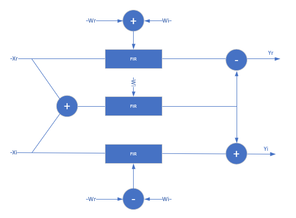
When both the data and coefficients are complex, the block implements three filters in parallel. The diagram show the filter implementation for complex input data X = Xr+i×Xi and complex coefficients W = Wr+i×Wi.
When Coefficients source is set to
Property
,
Wr +
Wi and
Wr-Wi
are pre-calculated, so this implementation uses 3 DSP blocks for each filter
tap, plus the input adder and two output adders. The input to each filter
tap multiplier grows by one bit.
When Coefficients source is set to Input
port
, the block uses 2 more adders for each filter tap.
These adders calculate the coefficients
Wr +
Wi and
Wr-Wi.
When you set the Filter structure parameter to
Direct form systolic
, the block implements
a fully parallel systolic architecture with optimizations for symmetry or
anti-symmetry and zero-valued coefficients. The latency depends on the
coefficient symmetry and is displayed on the block icon.
When symmetric pairs of coefficients have equal absolute values, they share one DSP block. This pair-sharing enables the implementation to use the pre-adder in Xilinx and Intel DSP blocks. The top half of the diagram shows a symmetric filter without the pair coefficient optimization. The bottom half of the diagram shows the architecture using the pair coefficient optimization.
This table shows post-synthesis resource utilization for the HDL code
generated for a symmetric 26-tap FIR filter with 16-bit input and
16-bit coefficients. The synthesis targets a Xilinx ZC-706 (XC7Z045ffg900-2) FPGA. The Global HDL
reset type is Synchronous
and Minimize clock enables is selected. The
reset port is not enabled, so only control
path registers are connected to the generated global HDL reset.
Resource | Uses |
---|---|
LUT | 36 |
Slice Reg | 487 |
Slice | 45 |
Xilinx LogiCORE DSP48 | 13 |
After place and route, the maximum clock frequency of the design is 630 MHz.
When you set the Filter structure parameter to
Direct form transposed
, the block
implements a fully parallel transposed architecture. This architecture
minimizes multipliers by sharing multipliers for any two or more
coefficients that have equal absolute values. It also removes multipliers
for zero-valued coefficients. The latency of the block is six cycles. This
latency does not change with coefficient values.
The top half of the diagram shows the theoretical architecture for a partly-symmetric filter without the equal-absolute-value coefficient optimization. The bottom half of the diagram shows the transposed architecture as implemented by this block, using the equal-value coefficient optimization. If the coefficients are antisymmetric, the output adder becomes a subtraction.
N
< L)When you set the Filter structure parameter to
Partly serial systolic
, and you choose a
serialization factor, N
, such that
N
is less than the number of coefficients
but greater than one, the block implements a partly serial systolic
architecture. The serial implementation uses
systolic cells.
Each cell consists of a delay line, coefficient lookup table, and DSP
(multiply-add) block. The coefficients are spread across the
M
=
ceil(L/N
)M
lookup tables. The computation performed
by each DSP block is serialized. Input samples to the block must be at least
N
cycles apart. The latency of the block is
M
+
ceil(
+
L/M
)5
.
This table shows post-synthesis resource utilization for the HDL code
generated from the Partly Serial Systolic FIR Filter Implementation example. The implementation is
for a 32-tap FIR filter with 16-bit input, 16-bit coefficients, and a
serialization factor of 8 cycles between valid input samples. The
synthesis targets a Xilinx Virtex-6 (XC6VLX240T-1FF1156) FPGA. The Global
HDL reset type is
Synchronous
and Minimize
clock enables is selected.
Resource | Uses |
---|---|
LUT | 192 |
FFS | 606 |
Xilinx LogiCORE DSP48 | 5 |
After place and route, the maximum clock frequency of the design is 376 MHz.
When you set the Filter structure parameter to
Partly serial systolic
, and you choose a
serialization factor such that
≥
N
, the block
implements a fully serial systolic architecture. In this case, the
implementation utilizes a single DSP (multiply-add) block with a delay line
and a lookup table for all L
L
coefficients. Input
samples must be at least N
cycles apart. The
latency of the block is L
+
5
.
Behavior changed in R2019a
The options for configuring a serial filter architecture have changed. Prior to R2019a, you specified the serial implementation by setting a requirement for input timing. Now, you can specify the serialization requirement based on either input timing (N) or resource usage (M).
Serial Filter Requirement | Configuration Prior to R2019a | Configuration After R2019a |
---|---|---|
Specify a serialization rule based on input timing, that is, N cycles. |
|
|
Specify a serialization rule based on resource usage, that is, M multipliers. | Serialization based on resource usage is not supported prior to R2019a. However, you can calculate N based on your multiplier requirement.
|
|
This block supports C/C++ code generation for Simulink accelerator and rapid accelerator modes and for DPI component generation.
HDL Coder™ provides additional configuration options that affect HDL implementation and synthesized logic.
For a FIR filter with multichannel or frame-based inputs, use the Discrete FIR Filter (Simulink) block instead.
The block provides three filter structures. The direct form systolic architecture provides a fully parallel implementation that makes efficient use of Intel and Xilinx DSP blocks. The direct form transposed architecture is a fully parallel implementation and is suitable for FPGA and ASIC applications. The partly serial systolic architecture provides a configurable serial implementation that also makes efficient use of FPGA DSP blocks. For a filter implementation that matches multipliers, pipeline registers, and pre-adders to the DSP configuration of your FPGA vendor, specify your target device when you generate HDL code.
All three structures optimize hardware resources by sharing multipliers for symmetric or antisymmetric filters. The parallel implementations also remove the multipliers for zero-valued coefficients such as in half-band filters and Hilbert transforms.
You can set block parameters to make tradeoffs between throughput and resource utilization.
For highest throughput, choose a fully parallel systolic or transposed architecture. The generated code can accept input data and provides filtered output data on every cycle.
For reduced area, choose partly serial systolic
architecture. Then specify a rule that the block
uses to serialize the filter based on either input
timing or resource usage. To specify a serial filter
using an input timing rule, set Specify
serialization factor as to
Minimum number of cycles between
valid input samples
, and choose
Number of cycles to be
greater than or equal to 2
.
In this case, the filter accepts only input samples
that are at least Number of
cycles cycles apart. To specify a
serial filter using a resource rule, set
Specify serialization factor
as to Maximum number of
multipliers
, and set
Number of multipliers to be
less than the number of filter coefficients. In this
case, the filter accepts input samples that are at
least NumCoeffs/NumMults
apart.
ConstrainedOutputPipeline | Number of registers to place at
the outputs by moving existing delays within your design. Distributed
pipelining does not redistribute these registers. The default is
|
InputPipeline | Number of input pipeline stages
to insert in the generated code. Distributed pipelining and constrained
output pipelining can move these registers. The default is
|
OutputPipeline | Number of output pipeline stages
to insert in the generated code. Distributed pipelining and constrained
output pipelining can move these registers. The default is
|
The Discrete FIR Filter HDL Optimized block does not support:
HDL code generation for floating-point input data types.
Vector inputs. The block is sample based, accepting one scalar at a time.
Resource sharing optimization through
HDL Coder. Instead, set the Filter
structure to Partly serial
systolic
, and configure a
serialization factor based on either input timing
or resource usage.