Export-Function Models Overview
Export-function models are Simulink® models that generate code for independent functions that can be integrated with an external environment and scheduler. Functions are defined using Function-Call Subsystem, function-call Model, Simulink Function, and S-Function blocks.
The following export-function model contains two functions defined with Function-Call Subsystem blocks. For a step-by-step procedure to create this model, see Create an Export-Function Model.

Code generated from this model has two independent functions, one for a delay function and the other for a square function.
      /*
       * File: export_function_model.c
       * Code generated for Simulink model 'export_function_model'.
       */

	void function_call_100ms(void)         /* Sample time: [0.1s, 0.0s] */
	{
	  export_function_model_Y.output_100ms =
	    export_function_model_DW.UnitDelay_DSTATE;

	  export_function_model_DW.UnitDelay_DSTATE =
	    export_function_model_Y.output_100ms + 1.0;
	}

      void function_call_10ms(void)          /* Sample time: [0.01s, 0.0s] */
	{
	    export_function_model_Y.output_10ms = export_function_model_U.input_10ms *
	    export_function_model_U.input_10ms;
	}
Workflows for Export-Function Models
Four common processes for creating export-function models differ in how you simulate and test your model before generating code for the functions.

When function-call sequencing is simple enough to be specified as a model input, simulation using an input matrix is the preferred method for testing an export-function model. See Test Export-Function Model Simulation Using Input Matrix.
When function-call sequencing is too complicated to specify with an input matrix, create a test model (harness) to mimic the target environment behavior. Use this test model to provide function-call inputs to the export-function model. See Test Export-Function Model Simulation Using Function-Call Generators, Test Export-Function Model Simulation Using Schedule Editor and Test Export-Function Model Simulation Using Stateflow Chart.
Allowed Blocks
At the top-level, an export-function model is limited to the following blocks:
Inport
Outport
Goto
From
Function-Call Subsystem
Function-call Model
Function-Call Split
Simulink Function
Initialize Function
Reset Function
Terminate Function
Data Store Memory
Bus Creator
Bus Selector
Mux
Demux
Merge
Signal Specification
S-Function
Requirements for Export Function Models
For an export-function model to successfully generate function code, the following requirements must be met.
Model Configuration Parameters:
Solver Type set to
Fixed-step.Solver set to
autoordiscrete.Code Generation System target file set to
ert.tlc. Selectingert.tlcrequires an Embedded Coder® license.For function-call Model blocks, Periodic sample time constraint for the referenced model set to
Ensure sample time
              independent
.
Root-level function-call Inport blocks:
Output function call check box selected.
Cannot receive a signal from an Asynchronous Task Specification block.
Root-level data Inport and Outport blocks cannot connect to virtual bus data signals.
Root-level Function-Call Subsystem blocks and function-call Model blocks:
All internal blocks within the block must support code generation.
If the Trigger block Sample time type is set to:
triggered, internal blocks must have Sample time set to-1.periodic, the root-level function-call Inport block must have its Sample time set to a specified discrete time and all internal blocks must have Sample time set to-1or the specified discrete time.
Sample Time for Function-Call Subsystems
In an export-function model, you can specify sample time for root-level function-call Inport blocks and the Trigger block inside a root-level Function-Call Subsystem block or function-call Model block. The following table shows how to specify these sample times.
| Trigger block Sample time type | Trigger block Sample time | Inport block Sample time | Function-call rate during simulation |
| Not specified, parameter is inactive. | -1 (inherited) | For simulation, the function-call initiator connected to the Inport block sets the rate of simulation. |
Specified discrete time | Function-call initiator, in test model, connected to Inport block must have a sample time equal to the specified discrete time for the Inport block. For simulation, component executes at the specified discrete rate. If a function-call source uses a different sample, Simulink displays an error message. | ||
Periodic function-call run-time checks apply if the export-function model is referenced from a Model block. | -1 (inherited) or the specified discrete time for the Inport block. | -1 (inherited) | This configuration is not allowed. Simulink displays an error message. |
Specified discrete time. | For simulation, component executes at the specified discrete sample time. If a function-call source uses a different sample time, Simulink displays an error message. |
Execution Order for Root-Level Function-Call Inport Blocks
By specifying sample time and priority for function-call Inport blocks you can control the execution order of Function-Call Subsystems and function-call Models during simulation. Alternatively, you can use the Schedule Editor or a Stateflow® chart to test scheduling. See Test Export-Function Model Simulation Using Schedule Editor and Test Export-Function Model Simulation Using Stateflow Chart.
Specify sample time for simulation execution. Right-click a function-call Inport block, then select Block parameters.
Select the Signal Attributes tab. In the Sample time box, enter a discrete time.
Specify the block priority for simulation. Right-click a function-call Inport block, then select Properties.
In the Priority box, enter a priority value.
Display block execution order for simulation. On the Debug tab, select Information Overlays
 , then from the drop-down dialog, select
Execution Order. This display has no impact on the generated
code.
, then from the drop-down dialog, select
Execution Order. This display has no impact on the generated
code.
In the following export-function model, Function-Call Subsystem 2 with
Sample time for Inport block 2 set to
0.01 (10 ms) runs before Function-Call Subsystem 1 with
Sample time for Inport block 1 set to
0.1 (100 ms).

Determine Relative Execution Order
Simulink compares function-call Inport block properties to determine their relative execution order using the following rules:
Priority – higher priority (lower number) executes first
Sample time – smaller sample time executes first
Port number – smaller port number executes first
When two blocks have different values for the Priority parameter, the block with the higher priority executes first. If the Priority parameter is equal, the block with the faster rate (smaller sample time) executes first. If Priority and sample time are the same for both of the blocks, the block with the lower port number executes first.
Note
When the simulation mode of the top model is Accelerator or Rapid Accelerator, Simulink does not perform run-time simulation checks for the execution order of root-level function-call Inport blocks inside referenced export-function models.
Suppose that an export function model has five root-level function-call Inport blocks, A to E, with block properties as shown in the table. To determine their relative execution order, Simulink compares their Priority parameters, sample times (if distinct and non-inherited), and port number.
| Root-level function-call Inport block | A | B | C | D | E |
|---|---|---|---|---|---|
| Priority | 10 | 30 | 40 | 40 | 30 |
| Sample Time | –1 | 0.2 | 0.1 | 0.1 | –1 |
| Port Number | 5 | 4 | 3 | 2 | 1 |
Block A has the highest priority of all five blocks. A executes first.
B and E execute after A but before C and D. Since B and E have the same priority, Simulink compares their sample times to determine execution order. E has a sample time of
-1(inherited), which is smaller than0.2, the sample time of B. E executes before B.C and D have the same priority and the same distinct, non-inherited sample times. The port number for D (2) is smaller than C (3), D executes before C.
The relative execution order for these function-call Inport blocks is A, E, B, D, and C.
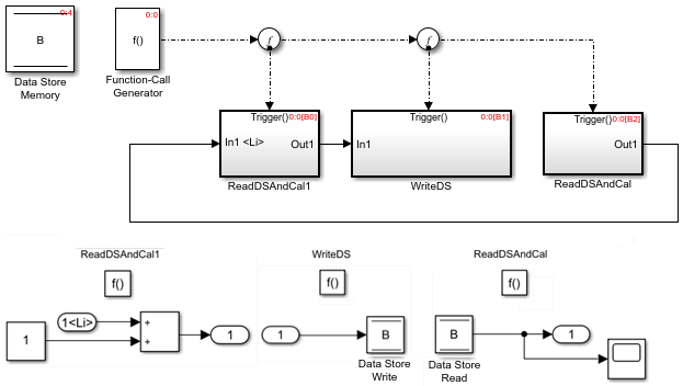
Latched Input Data for Function-Call Subsystems
You can latch input data for Inport blocks within Function-Call Subsystem blocks to ensure data integrity. To latch input data, select the Latch input for feedback signals of function-call subsystem outputs check box.
In the following model, input data for the Inport block in the
function-call subsystem ReadDSAndCal1 is latched (indicated by
<Li>) and cannot change during the execution of the subsystem. The
Data Store Read and Data Store Write blocks are called
within each function-call subsystem. The first and second function-calls write data and the
last function-call reads data to the Data Store Memory block.
Note
The root-level data Inport block connected to an internal Inport block is also latched if all of the blocks connected to the root-level block are latched. For more information, see Latch input for feedback signals of function-call subsystem outputs.
Note
Data transfer signals are unprotected in the generated code by default. Use custom storage classes to prevent data corruption in these signals due to preemption of the current task in the target environment.
Nested Export-Function Models
Nested export-function models provide an additional layer of organization. The following model has two referenced export-function models that are referenced from a Model block.

Note
An export-function model cannot contain a referenced model with asynchronous function-call inputs, but can contain function-call subsystems and function-call models. A model with asynchronous function-call inputs can contain an export-function model, a function-call subsystem, or a function-call model.
Export-Function Model with a Multi-Instanced Function-Call Model
You can use Function-Call Subsystem blocks or function-call Model blocks within an export-function model. If you use a function-call Model block, you can also create multiple instances of the model.
Define your algorithm with a model that contains a Trigger block. Set Trigger type to
function-call.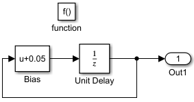
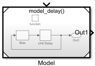
Reference the model from a Model block. The result is a function-call model.
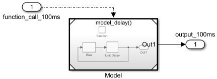
Connect a function-call Inport block and select the Output function call check box. Add signal Inport and Outport blocks. Update the model (Ctrl-D). The result is an export-function model with a function-call model.
Copy the referenced model and port blocks to create a second instance of the model. Execution order shows the first instance runs before the second instance.

Export-Function Models and Models with Asynchronous Function-Call Inputs
An export-function models capability is available for models with asynchronous function-call input ports. You use these models primarily in the Simulink environment where the Simulink scheduler calls the functions.
| Comparison Characteristic | Export-Function Models | Models with Asynchronous Function-Call Inputs |
|---|---|---|
| Definition | These models have root-level function-call Inport blocks that are not connected to an Asynchronous Task Specification block. These Inport blocks trigger function-call subsystems or function-call models (Model block with Trigger block). | These models have root-level function-call Inport blocks connected to Asynchronous Task Specification blocks. These Inport blocks trigger function-call subsystems or function-call models. |
| Root-level blocks | Only blocks executing in a function-call context are allowed at the root level. | Blocks executing in a non-function-call context are also allowed. |
| Data transfer | Use data transfer indicators to interpret simulation results. Data transfer in export-function models is not protected by default in generated code. For more details, see Latched Input Data for Function-Call Subsystems. | Use Rate Transition blocks to protect data transferred between function-call subsystems running at different rates. For more information, see Rate Transition. |
| Simulation support | These models support standalone simulation and test model simulation in all simulation modes. | These models support test model simulation in all simulation modes and standalone simulation in Normal, Accelerator, and Rapid Accelerator modes. |
| Code generation support | Top-model and standalone code generation are supported. | Top-model and standalone code generation are supported. |
See Also
Blocks
Related Topics
- Create an Export-Function Model
- Test Export-Function Model Simulation Using Input Matrix
- Test Export-Function Model Simulation Using Function-Call Generators
- Test Export-Function Model Simulation Using Stateflow Chart
- Test Export-Function Model Simulation Using Schedule Editor
- Generate Code for Export-Function Model