Generate HDL Code from Simulink Model
This example shows how you can generate HDL code for a simple
Counter model. The model is a simple up counter that counts
up from zero to a threshold value and then wraps back to zero. Before you generate
HDL code for this model, it is recommended that you verify the HDL compatibility of
your model by using the HDL Code Advisor. To learn how to:
Create this counter model, see Create Simulink Model for HDL Code Generation.
Check HDL compatibility of the counter model, see Check HDL Compatibility of Model Using HDL Code Advisor.
By default, HDL Coder™ creates an hdlsrc folder in the current working
folder to generate the HDL files. Therefore, before you proceed to generate HDL
code, make sure that your current working folder is writeable.
Simple Up Counter Model
Open this model to see a simple up counter. The model counts up from zero to a threshold value and then wraps back to zero. In this model, the threshold value is set to 15. You can change the threshold value by changing the value of the Constant block that is input to the count_threshold port. The Enable signal specifies whether the counter should count up or hold the previous value. The Enable signal is set to 1 which means that the counter counts upwards continuously.
open_system('hdlcoder_simple_up_counter.slx')
set_param('hdlcoder_simple_up_counter', 'SimulationCommand', 'Update')

Generate HDL Code
To generate code, you use the HDL Code tab in the To open the HDL Code Advisor, Select the DUT Subsystem and then click HDL Code Advisor.
For the up counter model, the HDL_DUT Subsystem is the DUT. To generate code for the DUT:
In the Apps tab, select HDL Coder. The HDL Code tab appears.
Select the DUT Subsystem in your model, and make sure that this Subsystem name appears in the Code for option. To remember the selection, you can pin this option. Click Generate HDL Code.
By default, HDL Coder generates VHDL code in the target hdlsrc
folder.
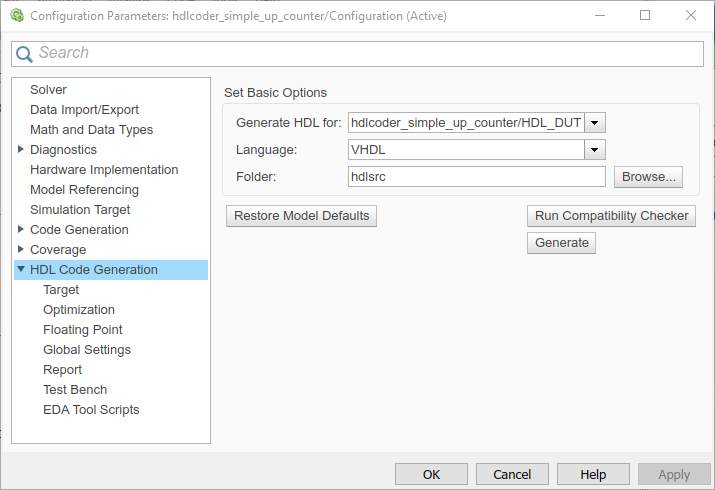
If you want to generate Verilog code, you can specify this setting in the HDL Code Generation pane of the Configuration Parameters dialog box. Before you generate code, you can also customize model-level settings for your design such as enable native floating-point support, generate resource and traceability reports, use model-level optimizations, and modify other global settings.
To generate Verilog code for the counter model:
In the HDL Code tab, click Settings.
In the HDL Code Generation pane, for Language, select
Verilog. Leave other settings to the default. Click Apply and then click Generate.
HDL Coder compiles the model before generating code. Depending on model display options such as port data types, the model can change in appearance after code generation. As code generation proceeds, HDL Coder displays progress messages in the MATLAB® command line with:
Link to the Configuration Set that indicates the model for which the Configuration Parameters are applied.
Links to the generated files. To view the files in the MATLAB Editor, click the links.
The process completes with the message:
### HDL Code Generation Complete.
View HDL Code Generation Files
A folder icon for the hdlsrc folder is now visible in the
Current Folder browser. To view generated code and script files, double-click
the hdlsrc folder icon. In the folder, you see a file
containing the VHDL or Verilog code, a script to compile the generated code, a
synthesis script, and a mapping file. For example, if you generated code for the
symmetric_fir Subsystem, you see these files in the
hdlsrc folder:
HDL_DUT.vhd: This file is the VHDL® code that contains the entity definition and RTL architecture implementing the up counter that you designed.Note
If you generated Verilog code, you get a
HDL_DUT.vfile.HDL_DUT_compile.do: Mentor Graphics® ModelSim® compilation script. To invoke this script and compile the generated VHDL code, you use thevcomcommand.HDL_DUT_synplify.tcl: This file is a Synplify® synthesis TCL script.HDL_DUT_map.txt: This report file is a mapping file that generated entities or modules to the subsystems that generated them. See Trace Code Using the Mapping File.HDL_DUT_report.html: This file is a HDL Code Generation Check report displays the status of HDL code generation and any warnings or messages. If HDL code generation fails, you see the cause of failure in the Check report.gm_hdlcoder_simple_up_counter.slx: This file is a generated model that behaviorally represents the HDL code in the Simulink® modeling environment. For more information, see Generated Model and Validation Model.
Verify Generated HDL Code
Before you proceed to deploy your design on the target hardware, you must
verify the generated HDL code. From the hdlsrc folder,
navigate to the current working folder. To learn how you can verify the
generated HDL code, see Verify Generated Code from Simulink Model Using HDL Test Bench.
See Also
hdlset_param | hdlsetup | makehdl