Create Simulink Model for HDL Code Generation
HDL Coder™ can generate VHDL and Verilog code from MATLAB® code, Simulink® models, and Stateflow® charts. You can then verify that the generated code matches your original algorithm, and deploy it on the target hardware.
This example illustrates how you can create a Simulink model for HDL code generation. The model is a simple up counter algorithm that wraps back to zero after it reaches the upper limit that you specify.
Open Model and HDL Coder Library
Start MATLAB. From the MATLAB toolstrip, click the Simulink button
 . Then, in the HDL
Coder section, select the Blank DUT
template.
. Then, in the HDL
Coder section, select the Blank DUT
template.Selecting this template opens a Simulink model that is preconfigured for HDL code generation. Save the model with a file name such as
hdlcoder_simple_up_counter.slxin a working folder that is writable.
When you create a model for HDL code generation, you partition the model into a Design-Under-Test (DUT) and a test bench. The DUT is a Subsystem that is mostly at the top level of your model, and contains the algorithm for which you generate HDL code. Blocks outside this Subsystem form the test bench, and contains inputs to the Subsystem and output values that are logged. The test bench ensures that the DUT functionality is as expected.
For the test bench, you can use blocks that are not supported for HDL code generation. In the Blank DUT template, the model has a HDL_DUT Subsystem that corresponds to the DUT. Blocks outside the HDL_DUT Subsystem form the test bench.
Open the HDL Coder Block Library for designing your counter algorithm. To filter the Simulink Library Browser to show block libraries that support HDL code generation, in the Apps tab, select HDL Coder. The HDL Code tab appears. Select HDL Block Properties > Open HDL Block Library.

In the HDL Coder library, you see several blocks that are pre-configured for HDL code generation. Blocks in this library are available with Simulink. If you do not have HDL Coder, you can simulate the blocks in your model, but cannot generate HDL code.
You can find additional HDL-supported blocks in these block libraries:
DSP System Toolbox HDL Support
Communications Toolbox HDL Support
Vision HDL Toolbox
Wireless HDL Toolbox
To restore the Library Browser to the default view, in the Library Browser, click the
 button.
Alternatively, at the MATLAB command-line, enter:
hdllib('off')Note
The set of supported blocks tend to change each release. Rebuild your supported blocks library each time you install a new version of this product.
Develop Design and Test Bench
Double-click the HDL_DUT Subsystem. Drag blocks from the HDL Coder library and add them to your model. This table illustrates the blocks to add to your model for designing the up counter. To learn about what a block does, and to specify the block parameters for that block, double-click the block.
Block Library Number of Blocks Block Parameters Constant Sources 2Constant values: 1 and 0
Output data type: uint32
Switch Signal Routing 2Criteria for passing first input: u2 > Threshold Delay Discrete 2Delay length: 1 Add Math Operations 1Accumulator data type: Inherit: Same as first input Relational Operator Logic and Bit Operations 1Relational operator: > Rename the input ports
In1andIn2tocount_thresholdandEnablerespectively. Place the blocks in your model and connect them as shown in figure.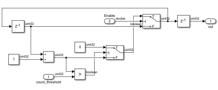
The
Enablesignal specifies whether the counter should count upwards from the previous value. When theEnablesignal is logic high, the counter counts up from zero to thecount_thresholdvalue. When the value ofoutbecomes equal to thecount_thresholdvalue, the counter wraps back to zero and starts counting again. When theEnablesignal becomes logic low, the counter holds the previous value.Navigate to the top level of the model and change the input settings.
Constant block input to
count_threshold: This input decides the maximum value up to which the counter should count. This example illustrates how to design a 4-bit up counter. Therefore, set the Constant value to15(2^4 - 1), and set the Output data type touint32.Note
Make sure that the output data type of this Constant block matches the output data type of the Constant blocks inside the HDL_DUT Subsystem.
Counter Free-Running block input to
Enable: For this example, remove the Counter Free-Running block. Replace this block with a Constant block that has a value of1and Output data type set toboolean.
This figure shows the top level of your model after you have applied these settings.

To learn more about how to create a model, see Create a Simple Model (Simulink).
Simulate and Verify Functionality of Design
Simulate your model by pressing the ![]() button. To see the simulation results, open
the Scope block at the top level of your model. The simulation
results display the
button. To see the simulation results, open
the Scope block at the top level of your model. The simulation
results display the Enable signal at the top generating a
constant value of 1 and the out signal
counting from 0 to 15, then wrapping back
to zero, and then counting up again. This figure displays the waveform of the
output signal out.

Check Model for HDL Compatibility
You have now simulated the model and verified the functionality of your design. Before you generate HDL code, you must verify that the model settings are compatible for HDL code generation. To make your design compatible for HDL code generation, you use the HDL Code Advisor. To learn how to use the HDL Code Advisor, see Check HDL Compatibility of Model Using HDL Code Advisor.
See Also
checkhdl | hdllib | hdlmodelchecker | hdlsetup