Autothreshold
Convert intensity image to binary image
Library
Conversions
visionconversions
Description
The Autothreshold block converts an intensity image to a binary image using a threshold value computed using Otsu's method.
This block computes this threshold value by splitting the histogram of the input image such that the variance of each pixel group is minimized.
| Port | Input/Output | Supported Data Types | Complex Values Supported |
|---|---|---|---|
I | Vector or matrix of intensity values |
| No |
BW | Scalar, vector, or matrix that represents a binary image | Boolean | No |
Th | Threshold value | Same as I port | No |
EMetric | Effectiveness metric | Same as I port | No |
Use the Thresholding operator parameter to specify the condition
the block places on the input values. If you select > and
the input value is greater than the threshold value, the block outputs
1 at the BW port; otherwise, it outputs 0. If
you select <= and the input value is less than or equal to
the threshold value, the block outputs 1; otherwise, it outputs
0.
Select the Output threshold check box to output the calculated threshold values at the Th port.
Select the Output effectiveness metric check box to output values that represent the effectiveness of the thresholding at the EMetric port. This metric ranges from 0 to 1. If every pixel has the same value, the effectiveness metric is 0. If the image has two pixel values or the histogram of the image pixels is symmetric, the effectiveness metric is 1.
If you clear the Specify data range check box, the block assumes that floating-point input values range from 0 to 1. To specify a different data range, select this check box. The Minimum value of input and Maximum value of input parameters appear in the dialog box. Use these parameters to enter the minimum and maximum values of your input signal.
Use the When data range is exceeded parameter to specify the block's behavior when the input values are outside the expected range. The following options are available:
Ignore— Proceed with the computation and do not issue a warning message. If you choose this option, the block performs the most efficient computation. However, if the input values exceed the expected range, the block produces incorrect results.Saturate— Change any input values outside the range to the minimum or maximum value of the range and proceed with the computation.Warn and saturate— Display a warning message in the MATLAB® Command Window, saturate values, and proceed with the computation.Error— Display an error dialog box and terminate the simulation.
If you clear the Scale threshold check box, the block uses the threshold value computed by Otsu's method to convert intensity images into binary images. If you select the Scale threshold check box, the Threshold scaling factor appears in the dialog box. Enter a scalar value. The block multiplies this scalar value with the threshold value computed by Otsu's method and uses the result as the new threshold value.
Fixed-Point Data Types
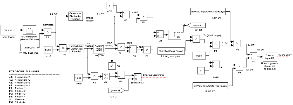
The following diagram shows the data types used in the Autothreshold
block for fixed-point signals. You can use the default fixed-point
parameters if your input has a word length less than or equal to 16.
In this diagram, DT means data type. You
can set the product, accumulator, quotient, and effectiveness metric
data types in the block mask.

Parameters
- Thresholding operator
Specify the condition the block places on the input matrix values. If you select
>or<=, the block outputs0or1depending on whether the input matrix values are above, below, or equal to the threshold value.- Output threshold
Select this check box to output the calculated threshold values at the Th port.
- Output effectiveness metric
Select this check box to output values that represent the effectiveness of the thresholding at the EMetric port.
- Specify data range
If you clear this check box, the block assumes that floating-point input values range from 0 to 1. To specify a different data range, select this check box.
- Minimum value of input
Enter the minimum value of your input data. This parameter is visible if you select the Specify data range check box.
- Maximum value of input
Enter the maximum value of your input data. This parameter is visible if you select the Specify data range check box.
- When data range is exceeded
Specify the block's behavior when the input values are outside the expected range. Your options are
Ignore,Saturate,Warn and saturate, orError. This parameter is visible if you select the Specify data range check box.- Scale threshold
Select this check box to scale the threshold value computed by Otsu's method.
- Threshold scaling factor
Enter a scalar value. The block multiplies this scalar value with the threshold value computed by Otsu's method and uses the result as the new threshold value. This parameter is visible if you select the Scale threshold check box.
- Rounding mode
Select the rounding mode for fixed-point operations. This parameter does not apply to the Cast to input DT step shown in Fixed-Point Data Types. For this step, Rounding mode is always set to
Nearest.- Overflow mode
Select the overflow mode for fixed-point operations.
- Product 1, 2, 3, 4

As shown previously, the output of the multiplier is placed into the product output data type and scaling. Use this parameter to specify how to designate the product output word and fraction lengths.
When you select
Specify word length, you can enter the word length of the product values in bits. The block sets the fraction length to give you the best precision.When you select
Same as input, the characteristics match those of the input to the block. This choice is only available for the Product 4 parameter.When you select
Binary point scaling, you can enter the word length and the fraction length of the product output in bits.When you select
Slope and bias scaling, you can enter the word length in bits and the slope of the product output. The bias of all signals in the Computer Vision Toolbox™ software is 0.
- Accumulator 1, 2, 3, 4

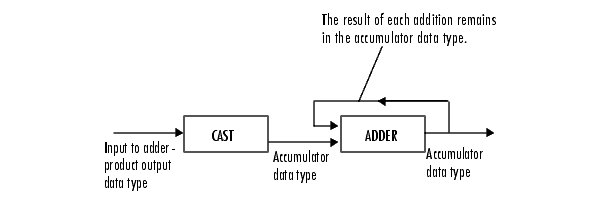
As shown previously, inputs to the accumulator are cast to the accumulator data type. The output of the adder remains in the accumulator data type as each element of the input is added to it. Use this parameter to specify how to designate the accumulator word and fraction lengths.
When you select
Same as Product, these characteristics match those of the product output.When you select
Specify word length, you can enter the word length of the accumulator values in bits. The block sets the fraction length to give you the best precision. This choice is not available for the Accumulator 4 parameter because it is dependent on the input data type.When you select
Binary point scaling, you can enter the word length and the fraction length of the accumulator in bits.When you select
Slope and bias scaling, you can enter the word length in bits and the slope of the accumulator. The bias of all signals in the Computer Vision Toolbox software is 0.
The Accumulator 3 parameter is only visible if, on the Main pane, you select the Output effectiveness metric check box.
- Quotient
Choose how to specify the word length and fraction length of the quotient data type:
When you select
Specify word length, you can enter the word length of the quotient values in bits. The block sets the fraction length to give you the best precision.When you select
Binary point scaling, you can enter the word length and the fraction length of the quotient, in bits.When you select
Slope and bias scaling, you can enter the word length in bits and the slope of the quotient. The bias of all signals in the Computer Vision Toolbox software is 0.
- Eff Metric
Choose how to specify the word length and fraction length of the effectiveness metric data type. This parameter is only visible if, on the Main tab, you select the Output effectiveness metric check box.
When you select
Specify word length, you can enter the word length of the effectiveness metric values, in bits. The block sets the fraction length to give you the best precision.When you select
Binary point scaling, you can enter the word length and the fraction length of the effectiveness metric in bits.When you select
Slope and bias scaling, you can enter the word length in bits and the slope of the effectiveness metric. The bias of all signals in the Computer Vision Toolbox software is 0.
- Lock data type settings against change by the fixed-point tools
Select this parameter to prevent the fixed-point tools from overriding the data types you specify on the block mask. For more information, see
fxptdlg(Fixed-Point Designer), a reference page on the Fixed-Point Tool in the Simulink® documentation.
Example
Convert an intensity image into a binary image. Use the Autothreshold block when lighting conditions vary and the threshold needs to change for each video frame.
You can open the example model by typing
on the MATLAB command line.
See Also
| Compare To Constant (Simulink) | Simulink |
| Relational Operator (Simulink) | Simulink |
graythresh | Image Processing Toolbox™ |
