Model Design for AXI4-Stream Interface Generation
With the HDL Coder™ software, you can implement a simplified, streaming protocol in your model. The software generates AXI4-Stream interfaces in the IP core.
Simplified Streaming Protocol
To map the DUT ports to AXI4-Stream interfaces, use the simplified AXI4-Stream
protocol. You do not have to model the actual AXI4-Stream protocol and instead you can
use the simplified protocol. When you run the IP Core Generation
workflow, the generated HDL code contains a wrapper logic that translates between the
simplified protocol and the actual AXI4-Stream protocol. The simplified protocol
requires you to use less protocol signals, eases the handshaking mechanism between valid
and ready signals, and supports bursts of arbitrary lengths.
Use the simplified AXI4-Stream protocol for both write and read transactions. When you want to generate an AXI4-Stream interface in your IP core, in your DUT interface, implement the following signals:
Data
Valid
Optionally, when you map scalar DUT ports to an AXI4-Stream interface, you can model the following signals:
Ready
Other protocol signals, such as:
TSTRBTKEEPTLASTTIDTDESTTUSER
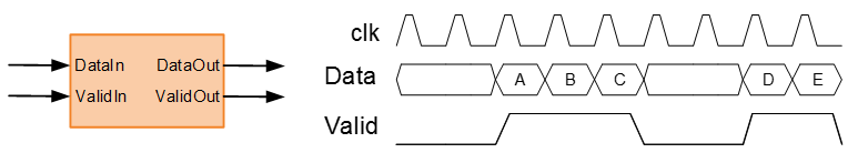
Data and Valid Signals
When the Data signal is valid, the Valid signal is asserted.
Note
This diagram illustrates the Data and Valid signal relationship according
to the simplified streaming protocol. When you run the IP Core
Generation workflow, HDL Coder adds a streaming interface module in the HDL IP core that
translates the simplified protocol to the full AXI4-stream protocol.
Map Scalar Ports To AXI4-Stream Interface
If you want to generate a hardware IP core, but do not need to model and simulate the interaction between the software and hardware, use scalar data ports at your DUT interface. Map the data ports to AXI4-Stream interfaces.
Data and Valid Signal Modeling Pattern
To model the Data and Valid signals in Simulink®:
Enclose the algorithm that processes the Data signal by using an enabled subsystem.
Control the enable port of the enabled subsystem by using the Valid signal.
For example, you can directly connect the Valid signal to the enable port.

You can also use a controller in your DUT that generates an enable signal for the enabled subsystem.

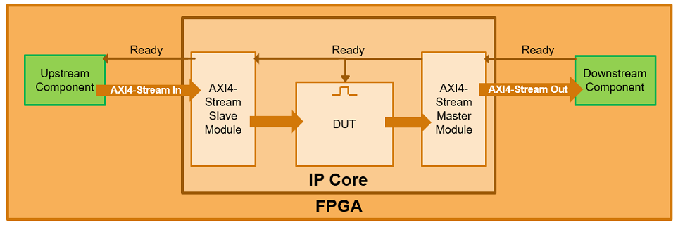
Ready Signal (Optional)
The AXI4-Stream interfaces in your DUT can optionally include a Ready signal. In a Slave interface, you use the Ready signal to apply back pressure. In a Master interface, you use the Ready signal to respond to back pressure.
By default, HDL Coder generates the Ready signal automatically. When you use a single streaming channel, HDL Coder also generates the logic that handles back pressure. The back pressure logic ties the Ready signal to the DUT Enable signal. When the input Master Ready signal goes low, the DUT is disabled, and the output slave Ready signal is driven low. Therefore, when you use a single streaming channel, the Ready signal is optional and you do not have to model this signal at the DUT port.
If you use multiple streaming channels, HDL Coder does not automatically generate the back pressure logic. In this case, the Ready signal is generated but the master Ready signal at the input is ignored and the slave Ready signal at the output is tied to high value. The absence of a back pressure logic can result in samples being dropped. If you want your design to apply back pressure on the Slave interface or respond to back pressure from the Master interface, you must model the Ready signal for each additional interface and then map the port to the Ready signal for that interface. When you do not model, the Set Target Interface task displays a warning that provides names of interfaces that require a Ready port. If your design does not need to apply or respond to back pressure, you can ignore this warning and you do not have to model the Ready signal.
If you model the Ready signal in your AXI4-Stream interfaces, your Master interface ignores the Data and Valid signals one clock cycle after the Ready signal is de-asserted. You can start sending Data and Valid signals once the Ready signal is asserted. You can send one more Data and Valid signal after the Ready signal is de-asserted.
If you do not model the Ready signal, HDL Coder generates the signal and the associated back pressure logic.
Note
This diagram illustrates the relationship between the Data, Valid, and
Ready signals according to the simplified streaming protocol. When you run
the IP Core Generation workflow, HDL Coder adds a streaming interface module in the HDL IP core that
translates the simplified protocol to the full AXI4-stream protocol.

For example, if you have a FIFO in your DUT to store a frame of data, to apply back pressure to the upstream component, you can model the Ready signal based on the FIFO Full signal.
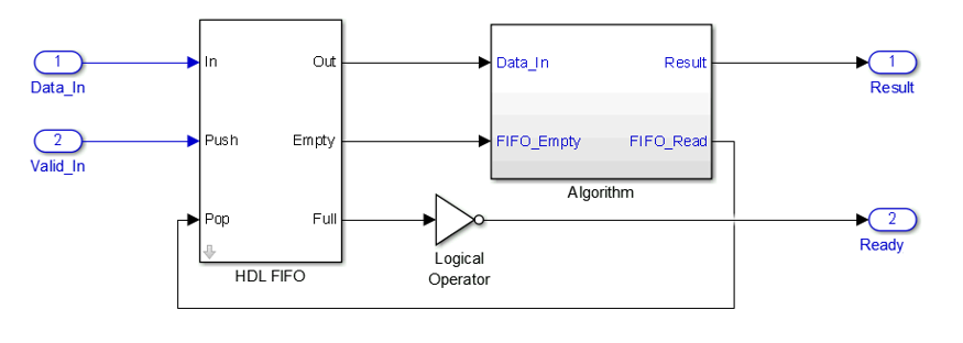
Note
If you enable delay balancing, the coder can insert one or more delays on the Ready signal. Disable delay balancing for the Ready signal path.
Other Protocol Signals (optional)
You can optionally model other AXI4-Stream protocol signals. If you model only the
required Data and Valid signals, the coder generates the TREADY
and TLAST AXI4-Stream protocol signals.
If you do not model the TLAST signal, the coder generates a
programmable register in the IP core so that you can specify your packet size. The
details of the programmable packet size register are in your IP core generation
report.
Map Vector Ports To AXI4-Stream Interface
If you want to model and simulate the system interaction between the software and hardware, and generate code for the software driver, use vector data ports at your DUT interface. Map the data ports to AXI4-Stream interfaces.
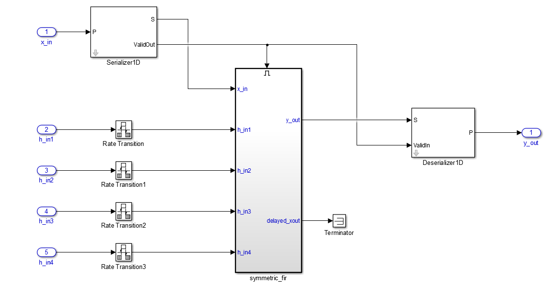
Data and Valid Signal Modeling Requirements
When you map vector ports to AXI4-Stream interfaces, your model has these requirements:
Connect each DUT input vector data port to a Serializer1D block.
The Serializer1D block must have a ValidOut port and the Ratio set to the vector bit width.
Connect each DUT output vector data port to a Deserializer1D block.
The Deserializer1D block must have a ValidIn port and the Ratio set to the vector bit width.
Connect each scalar port that maps to an AXI4-Lite interface to a Rate Transition block.
The Ratio in the Rate Transition block must match the Ratio in the Serializer1D and Deserializer1D blocks.
Each scalar port that maps to an external port must have the same sample time as the streaming algorithm subsystem.
The streaming algorithm subsystem follows the same Data and Valid signal modeling pattern as for mapping scalar ports to an AXI4-Stream interfaces. See Data and Valid Signal Modeling Pattern.
Example
For an example that shows how to map vector ports to AXI4-Stream interfaces, open
the hdlcoder_sfir_fixed_vector model. In the
hdlcoder_sfir_fixed_vector model,
symmetric_fir is the streaming algorithm subsystem.
Model Designs with Multiple Streaming Channels
When you run the IP Core Generation workflow, you can map multiple
scalar DUT ports to AXI4-Stream Master and AXI4-Stream Slave channels. When you use
vector ports, you can map the ports to at most one AXI4-Stream Master channel and one
AXI4-Stream Slave channel.
Note
If you use multiple streaming channels, HDL Coder generates the Ready signal but does not generate the back pressure logic. If you want your design to handle back pressure, model the Ready signal in your design.
To learn more, see Generate HDL IP Core with Multiple AXI4-Stream and AXI4 Master Interfaces.
Model Designs with Multiple Sample Rates
The HDL Coder software supports designs with multiple sample rates when you run the
IP Core Generation workflow. When you map the interface ports to
AXI4-Stream Master or AXI4-Stream Slave interfaces, to use multiple sample rates, ensure
that the DUT ports that map to these AXI4 interfaces run at the fastest rate of the
design after HDL code generation.
To learn more, see Multirate IP Core Generation.
Restrictions
When you map scalar or vector DUT ports to AXI4-Stream interfaces:
Xilinx® Zynq®-7000 or Intel® Quartus® Prime must be your target platform.
Xilinx Vivado® or Intel Quartus Prime must be your synthesis tool.
Processor/FPGA synchronization must be
Free running.
When you map vector DUT ports to AXI4-Stream interfaces, you cannot use protocol signals other than Data and Valid. For example, Ready and TLAST are not supported.
Related Topics
- Hardware-Software Co-Design Workflow for SoC Platforms
- Generate Board-Independent HDL IP Core from Simulink Model