Model Design for AXI4 Slave Interface Generation
To perform lightweight data transfer or to access control registers, use AXI4 slave interfaces. The AXI4 slave interfaces include the AXI4 and AXI4-Lite interfaces. With the HDL Coder™ software, you don't have to implement AXI4 or AXI4-Lite protocol in your model. The software generates AXI4 or AXI4-Lite interfaces in the HDL IP core.
When you model your design, specify the data ports that you want to map to the AXI4 slave interfaces. HDL Coder then maps the data ports to memory-mapped AXI4 slave interfaces and allocates address offsets for the ports.
Considerations
When you map your DUT ports to AXI4 or AXI4-Lite interfaces:
You can map all scalar or vector ports in your design to either AXI4 or AXI4-Lite interfaces. You cannot map some DUT ports to AXI4 interfaces and other DUT ports to AXI4-Lite interfaces for the same design.
You can use a single-rate design or a design with multiple sample rates without any restrictions when mapping the DUT ports to AXI4 slave interfaces by using the
Free Runningsynchronization mode for Processor/FPGA Synchronization.You can use the
Coprocessing-Blockingmode for Processor/FPGA Synchronization when mapping to AXI4 or AXI-Lite interfaces. Other interface types such as AXI4-Stream and AXI4 Master do not support this mode. See also Processor and FPGA Synchronization.
Map Scalar Ports to AXI4 Slave Interface
When you use scalar data types at the DUT interface ports, you can map the interface ports directly to AXI4 or AXI4-Lite interfaces. The code generator assigns a unique address to each data port that you want to map to the AXI4 interface.
For an example that shows how to map scalar ports to AXI4-Lite interfaces, open the
model
hdlcoder_led_blinking.
open_system('hdlcoder_led_blinking')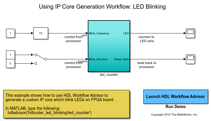
In this model, the subsystem led_counter is the hardware subsystem.
It models a counter that blinks the LEDs on an FPGA board. Two input ports,
Blink_frequency and Blink_direction, are
control ports that determine the LED blink frequency and direction. All the blocks
outside of the subsystem led_counter are for software
implementation.
In Simulink®, you can use the Slider Gain block or the Manual
Switch block to adjust the input values of the hardware subsystem. In the
embedded software, this means that the ARM processor controls the generated IP core by
writing to the AXI interface accessible registers. The output port of the hardware
subsystem connects to the LED hardware. You can use the output port
Read_back to read data back to the processor.
When you run the IP Core Generation workflow, in the Set
Target Interface task, you see that the ports
Blink_frequency, Blink_direction, and
Read_back map to AXI4-Lite interfaces.
To learn more about this example, see:
Map Vector Ports to AXI4 Slave Interface
When you use vector data types at the DUT interface ports, you can map the interface ports directly to AXI4 or AXI4-Lite interfaces. The code generator assigns a unique address for each data port that you want to map to the AXI4 interface.
When you map vector ports, HDL Coder uses additional strobe registers for each port to maintain the synchronization with the IP core algorithm logic. For input ports, the strobe registers control the enable signals for a set of shadow registers, which makes the IP core algorithm logic see the updated vector elements simultaneously. For output ports, the strobe registers make sure that the vector data to be read is captured synchronously.
For an example that shows how to map vector ports to AXI4-Lite interfaces, open the
model
hdlcoder_led_vector.
open_system('hdlcoder_led_vector')
In this model, the subsystem DUT implements the LED blinking
algorithm and has vector output ports. When you run the IP Core
Generation workflow, in the Set Target Interface
task, you see that the input ports and output ports map to AXI4-Lite interfaces.
To learn more, see IP Core Generation Workflow with a MicroBlaze processor: Xilinx Kintex-7 KC705.
Initial Value of AXI4 Slave Registers
When you run the IP Core Generation workflow or the
Simuilnk Real-Time FPGA I/O workflow, you can specify an initial
value for the AXI4 slave registers. You can specify an initial value when mapping scalar
and vector input and output ports to these target interfaces.
AXI4
AXI4-Lite
PCIe
By default, the initial value is zero. To specify a nonzero value:
In the target platform interface table, when you map DUT port to an AXI4 slave interface, an Options button appears in the Interface Options column.
Click the Options button and then specify the RegisterInitialValue.
The specified value is saved on the DUT Inport and Outport blocks as the HDL block property
IOInterfaceOptions in the Target
Specification tab. For example, if you map a DUT input port to AXI4-Lite
interface, set RegisterInitialValue to 5, and
then run this task, the IOInterfaceOptions property of that input
port is saved with the value {'RegisterInitialValue','5'}.
To view the IOInterfaceOptions value, if the full path to your
DUT port is hdlcoder_led_blinking/led_counter/LED,
enter:
hdlget_param('hdlcoder_led_blinking/led_counter/LED',...
             'IOInterfaceOptions')
This example shows how you specify the initial value for vector ports.
hdlset_param('sfir_fixed_stream/DUT/In2', ...
     'IOInterfaceOptions', {'RegisterInitialValue','[3.5 3.5 3.5]'});
Read Back Value of AXI4 Slave Interfaces
When you run the IP Core Generation workflow, you can read back the
value that is written to the AXI4 slave registers by using the AXI4 slave interface. For
example, you can read back the values that are written to the AXI4 slave registers by
using the devmem command in the Linux console of the ARM processor.
If you have HDL Verifier™ installed, you can use the MATLAB as AXI Master IP to read back the
values.
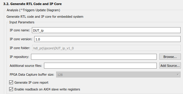
To use this capability, in the Generate RTL Code and IP Core task
of the IP Core Generation workflow, select the Enable read
back on AXI4 slave write registers check box, and then run this task.
When you run this task, HDL Coder saves the read back setting that you enabled on the model. In the HDL
Block Properties of the DUT Subsystem, on the IP Core Parameter
section of the Target Specification tab, you see a parameter
AXI4RegisterReadback set to on. If you
export the HDL Workflow Advisor run to a script, you see this setting saved on the model
by using
hdlset_param.
hdlset_param('hdlcoder_led_vector/DUT', 'AXI4RegisterReadback', 'on');
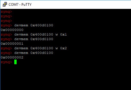
These examples show how you can read back values by using the
devmem command in the Linux console with a program such as
PuTTy™.
To read back values when mapping scalar ports to AXI4 interfaces, you first write values to the AXI4 registers, and then read back the values. You can see the memory address of the AXI4 registers in the IP Core Generation report.
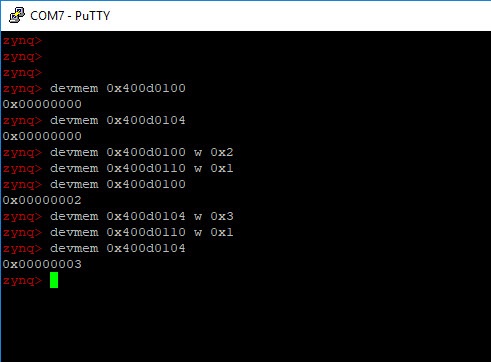
To read back values when mapping vector ports to AXI4 interfaces, you first write to
the AXI4 registers, then write the strobe register address with 0x1,
and then read back the values. You can see the memory address of the AXI4 registers and
the strobe register in the IP Core Generation report.
Optimize AXI4 Slave Read Back Logic
When your model contains several output registers and you want to read back data from multiple AXI4 slave registers, the read back logic becomes a long mux chain that can reduce the synthesis frequency. If you select the Enable readback on AXI4 slave write registers setting in the Generate RTL Code and IP Core task, HDL Coder adds a mux for each AXI4 register in the Address Decoder logic. As the number of AXI4 slave registers increases, the mux chain becomes longer, which further reduces the synthesis frequency.
You can optimize the readback logic and achieve the target frequency that you want.
When you run the IP Core Generation workflow, in the
Generate RTL Code and IP Core task, you see a setting
AX4 slave port to pipeline register ratio. The default value of
this setting is auto. This setting indicates how many AXI4 slave
registers a pipeline register is inserted for. For example, an AX4 slave port
to pipeline register ratio of 20 means that one
pipeline register is inserted for every 20 AXI slave registers. The
auto setting means that the code generator inserts a certain
number of pipelines for the AXI4 slave ports depending on the number of ports and the
synthesis tool that you specify. You can disable this setting or select a number between
5 and 50 for this ratio.
When you run this task, HDL Coder saves the value that you specified for the setting on the model. In the
HDL Block Properties of the DUT Subsystem, on the IP Core Parameter
section of the Target Specification tab, you see a parameter
AX4SlavePortToPipelineRegisterRatio set to the value that you
specified. If you export the HDL Workflow Advisor run to a script, you see this setting
saved on the model by using
hdlset_param.
hdlset_param('hdlcoder_led_vector/DUT', ...
                    'AXI4SlavePortToPipelineRegisterRatio', '20');