FIR Rate Conversion HDL Optimized
Upsample, filter, and downsample input signals—optimized for HDL code generation
Library
DSP System Toolbox HDL Support > Filtering
dsphdlfiltering
Description
The FIR Rate Conversion HDL Optimized block upsamples, filters, and downsamples input signals. It is optimized for HDL code generation and operates on one sample of each channel at a time. The block implements an efficient polyphase architecture to avoid unnecessary arithmetic operations and high intermediate sample rates.

The block upsamples by an integer factor of L, applies an FIR filter, and downsamples by an integer factor of M.
The block has input and output control ports for pacing the flow of samples. In the
default configuration, the block uses validIn and
validOut control signals. For additional flow control, you can
enable a ready output signal and a request input
signal.

The ready output port indicates that the block can accept a new
input data sample on the next time step. When L ≥
M, you can use the ready signal to achieve
continuous output data samples. If you apply a new input sample after each time the
block returns ready = true, the block returns a
data output sample with validOut = true on every
time step.
When you do not enable the ready port, you can apply a valid data
sample only every ceil(L/M) time steps. For example:
L/M = 4/5 — You can apply a new input sample on every time step.
L/M = 3/2 — You can apply a new input sample on every other time step.
When you enable the request input port, the block returns the next
output sample when request is true and a valid
output sample is available. When you do not use request , the block
returns output samples when they are available. When no new data is available, the block
returns validOut = false.
You can connect the request input port to the
ready output port of a downstream block.
Signal Attributes
This icon shows all the optional ports of the FIR Rate Conversion HDL
Optimized block. ![]()
| Port | Direction | Description | Data Type |
|---|---|---|---|
dataIn | Input | Data sample, specified as a scalar, or as a row vector in which each element represents an independent channel. The block accepts real or complex data. |
|
validIn | Input | Capture the value of dataIn, when
validIn is true. You can
apply a valid data sample every ceil(L/M) time
steps. | boolean |
request | Input (Optional) | Request for a new output sample. | boolean |
dataOut | Output | Resampled and filtered data sample, returned as a scalar, or as a vector in which each element represents an independent channel. | Same as dataIn |
validOut | Output | Qualification of the dataOut value. When
validOut is true,
dataOut is valid. | boolean |
ready | Output (Optional) | Indicates that the block is ready for a new input sample, when
ready is true. | boolean |
Parameters
Main
- Interpolation factor
Upsampling factor, L, specified as a scalar integer. The default is 3.
- Decimation factor
Downsampling factor, M, specified as a scalar integer. The default is 2.
- FIR filter coefficients
Filter coefficients, specified as a vector in descending powers of z-1.
You can generate filter coefficients using the Signal Processing Toolbox™ filter design functions (such as
fir1). Design a lowpass filter with normalized cutoff frequency no greater thanmin(1/L,1/M). The block initializes internal filter states to zero. The default coefficients arefirpm(70,[0 .28 .32 1],[1 1 0 0]).- Enable ready output port
Select this check box to enable a port that indicates when the block is able, on the next time step, to accept a new input data sample.
- Enable request input port
Select this check box to enable a port that requests the block return an output sample. When the
requestport istrue, and there is an output sample available, the block returns a new output sample and setsvalidOuttotrue. Whenrequestisfalse, or there is no new sample available, the block setsvalidOuttofalse.
Data Types
- Rounding mode
The default rounding method for internal fixed point calculations is
Floor.Simplestrounding mode is not supported.- Saturate on integer overflow
The default Overflow Handling for internal fixed point calculations is wrap.
- Coefficients Data Type
Data type of the FIR filter coefficients, specified as a
fixdt(s,wl,fl)object withsignedness,word length, andfractional lengthproperties. The default isfixdt(1,16,16).- Output Data Type
Data type of the output data samples. You can choose
Inherit: Inherit via internal rule,Inherit: Full precision, or specify afixdt(s,wl,fl)object. The default isInherit: Same word length as input.
Examples
Downsample a Signal
Convert a signal from 48 kHz to 32 kHz using the FIR Rate Conversion HDL Optimized block.
The source is a cosine input signal, sampled at 48kHz. The model passes a new data sample into the block on every time step by holding validIn = true. After resampling, the validOut signal is true on only 2/3 of the time steps.
Open the Model

Configure the Model
Define the data rate parameters in the InitFcn callback.

Configure the FIR Rate Conversion HDL Optimized block. Use the default interpolation factor of 2 and decimation factor of 3. Use the firmpm function to design an equiripple FIR filter. In the Data Types group, set the Coefficients data type to fixdt(1,16,15) to accommodate the filter you designed.
Run the Model and Display Results
Run the model. Use the Logic Analyzer to view the input and output signals of the block. The blue icon in the model indicates streamed signals. Launch the Logic Analyzer from the model's toolbar.

In the Logic Analyzer, note the pattern of validIn and the resulting validOut signal.

Generate HDL Code
To generate HDL code from the FIR Rate Converter HDL Optimized block, right-click the block and select Create Subsystem from Selection. Then right-click the subsystem and select HDL Code > Generate HDL Code for Subsystem.
Control Data Rate Using the Ready and Request Ports
Convert a signal from 40 MHz to 100 MHz using the FIR Rate Converter HDL Optimized block. Uses the optional request input signal and ready output signal to control the data rate.
To represent a system clock rate of 200MHz, the model connects a repeating true-false signal to the
requestport. This configuration generates output samples at 100 MHz, i.e. every second time step. Alternatively, you can connect this port to thereadyport of a downstream block.When the block can accept a new input sample on the next time step, it sets the
readyoutput signal totrue. The model connects this signal to a waveform source that generates one sample at a time.
Open the Model

Configure the Model
Define the data rate parameters in the InitFcn callback.

Configure the FIR Rate Conversion HDL Optimized block. Use an interpolation factor of 5 and a decimation factor of 2. Use the firmpm function to design an equiripple FIR filter. Select both check boxes to enable the ready and request ports. % In the Data Types group, set the Coefficients data type to fixdt(1,16,15) to accommodate your filter design.
Run the Model and Display Results
Run the model. Use the Logic Analyzer to view the input and output signals of the block. The blue icon in the model indicates streamed signals. Launch the Logic Analyzer from the model's toolbar.
In the Logic Analyzer, note the pattern of request and the resulting validOut signal, and the pattern of ready and the resulting validIn signal.

Generate HDL Code
To generate HDL code from the FIR Rate Converter HDL Optimized block, right-click the block and select Create Subsystem from Selection. Then right-click the subsystem and select HDL Code > Generate HDL Code for Subsystem.
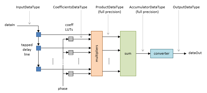
Algorithm
The FIR Rate Conversion HDL Optimized block implements a fully parallel polyphase filter architecture. The diagram shows where the block casts the data types, according to your configuration.
Delay
The block models HDL pipeline latency, so there is an initial delay of several
time steps before the object returns the first valid output sample. The latency
depends on the filter coefficients and the resampling factors. To determine the
latency from first sample in to first sample out, observe the
validOut signal.
Performance
For a sample of design performance, generate HDL for the block as configured in the Control Data Rate Using the Ready and Request Ports example. The example filter resamples at 5/2, and uses a symmetric 71-tap filter. The input samples and filter coefficients are 16 bits wide. The design was targeted to a Xilinx® Virtex®-6 FPGA, using Xilinx ISE synthesis and place and route tools.
After place and route, the design achieves 535 MHz clock frequency. It uses these resources.
| LUT | 592 |
| FFS | 979 |
Xilinx LogiCORE® DSP48 | 15 |
| Block RAM (16K) | 0 |
Performance of the synthesized HDL code varies depending on your filter coefficients, FPGA target, and synthesis options.