Sun-Planet Worm Gear

Planetary gear set of carrier, worm planet, and sun wheels with adjustable gear ratio, worm thread type, and friction losses

  • Library:
  • Simscape / Driveline / Gears / Planetary Subcomponents

  • Sun-Planet Worm Gear block

Description

The Sun-Planet Worm Gear block represents a two-degree-of-freedom planetary gear built from carrier, sun, and planet gears. By type, the sun and planet gears are crossed helical spur gears arranged as a worm-gear transmission, in which the planet gear is a worm. Such transmissions are used in the Torsen type 1 differential. When transmitting power, the sun gear can be independently rotated by the worm (planet) gear, or by the carrier, or by both.
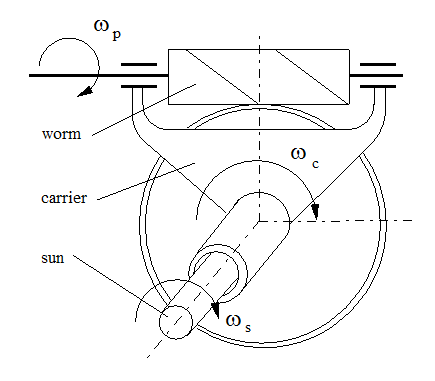
You specify a fixed gear ratio, which is determined as the ratio of the worm angular velocity to the sun gear angular velocity. You control the direction by setting the worm thread type, left-hand or right-hand. Rotation of the right-hand worm in positive direction causes the sun gear to rotate in positive direction too. The positive directions of the sun gear and the carrier are the same.

Thermal Model

You can model the effects of heat flow and temperature change by exposing an optional thermal port. To expose the port, in the Meshing Losses tab, set the Friction model parameter to Temperature-dependent efficiency.

Equations

Variables

Equation variables are:

  • RWG is the gear, or transmission, ratio determined as the ratio of the worm angular velocity to the gear angular velocity. The ratio is positive for the right-hand worm and negative for the left-hand worm.

  • ωS is the angular velocity of the sun gear.

  • ωP is the planet (that is, worm) angular velocity.

  • ωC is the carrier angular velocity.

  • ωSC is the angular velocity of the sun with respect to the carrier.

  • α is the normal pressure angle.

  • λ is the worm lead angle.

  • L is the worm lead.

  • d is the worm pitch diameter.

  • τS is the torque applied to the sun shaft.

  • τP is the torque applied to the planet shaft.

  • τC is the torque applied to the carrier shaft.

  • τ is the torque loss due to meshing friction. The loss depends on the device efficiency and the power flow direction. To avoid abrupt change of the friction torque at ωS = 0, the friction torque is introduced via the hyperbolic function.

  • τinstfr is the instantaneous value of the friction torque added to the model to simulate friction losses.

  • τfr is the steady-state value of the friction torque.

  • k is the friction coefficient.

  • ηWG is the efficiency for worm-gear power transfer.

  • ηGW is the efficiency for gear-worm power transfer.

  • pth is the power threshold.

  • μSC is the sun-carrier viscous friction coefficient.

  • μWC is the worm-carrier viscous friction coefficient.

Ideal Gear Constraints and Gear Ratio

The sun-planet worm gear imposes one kinematic constraint on the three connected axes:

ωS=ωPRWG+ωC

The gear has two independent degrees of freedom. The gear pair is (1,2) = (S,P).

The torque transfer is:

RWGτP+τSτloss= 0

τC= τS

In the ideal case, there is no torque loss, that is τloss = 0.

Nonideal Gear Constraints

In the nonideal case, τloss ≠ 0. For more information, see Model Gears with Losses.

In a nonideal gear, the angular velocity and geometric constraints are unchanged. But the transferred torque and power are reduced by:

  • Coulomb friction between thread surfaces on W and G, characterized by friction coefficient k or constant efficiencies [ηWG, ηGW]

  • Viscous coupling of driveshafts with bearings, parametrized by viscous friction coefficients μSC and μWC

Because the transmission incorporates a worm gear, the efficiencies are different for the direct and reverse power transfer. The following table shows the value of the efficiency for all combinations of the power transfer.

Driving ShaftDriven Shaft
PlanetSunCarrier
Planetn/aηWGηWG
SunηGWn/aNo loss
CarrierηGWNo lossn/a
Geometric Surface Contact Friction

In the contact friction case, ηWG and ηGW are determined by:

  • The worm-gear threading geometry, specified by lead angle λ and normal pressure angle α.

  • The surface contact friction coefficient k.

ηWG= (cosαk·tanλ)(cosα+ktanλ)

ηGW= (cosαktanλ)(cosα+k·tanα)

Constant Efficiencies

In the constant efficiency case, you specify ηWG and ηGW, independently of geometric details.

Self-Locking and Negative Efficiency

If you set efficiency for the reverse power flow to a negative value, the train exhibits self-locking. Power cannot be transmitted from sun gear to worm and from carrier to worm unless some torque is applied to the worm to release the train. In this case, the absolute value of the efficiency specifies the ratio at which the train is released. The smaller the train lead angle, the smaller the reverse efficiency.

Meshing Efficiency

The efficiencies η of meshing between worm and gear are fully active only if the transmitted power is greater than the power threshold.

If the power is less than the threshold, the actual efficiency is automatically regularized to unity at zero velocity.

Viscous Friction Force

The viscous friction coefficients of the worm-carrier and sun-carrier bearings control the viscous friction torque experienced by the carrier from lubricated, nonideal gear threads. For details, see Nonideal Gear Constraints.

Variables

Use the Variables settings to set the priority and initial target values for the block variables before simulating. For more information, see Set Priority and Initial Target for Block Variables.

Dependencies

Variable settings are exposed only when, in the Meshing Losses settings, the Friction model parameter is set to Temperature-dependent efficiency.

Limitations and Assumptions

  • Gear inertia is assumed negligible.

  • Gears are treated as rigid components.

  • Coulomb friction slows down simulation. For more information, see Adjust Model Fidelity.

Ports

Conserving

expand all

Rotational conserving port associated with the planet gear carrier.

Rotational conserving port associated with the worm gear.

Rotational conserving port associated with the sun gear.

Thermal conserving port associated with heat flow. Heat flow affects gear temperature, and therefore, power transmission efficiency.

Dependencies

This port is exposed when, in the Meshing Losses settings, the Friction parameter is set to Temperature-dependent efficiency.

Exposing this port also exposes related parameters.

Parameters

expand all

Main

Gear or transmission ratio RWG determined as the ratio of the worm angular velocity to the gear angular velocity. This gear ratio must be strictly positive.

Directional sense of gear rotation corresponding to positive worm rotation. If you select Left-hand, rotation of the worm in the generally-assigned positive direction results in the gear rotation in negative direction.

Meshing Losses

The table shows how the options that you choose for the Shaft settings affect the visibility of other parameters in the Shaft settings. To learn how to read the table, see Parameter Dependencies.

Meshing Losses Parameter Dependencies

Meshing Losses Setting Parameters and Values
Friction Model
No meshing losses - Suitable for HIL simulationConstant efficiencyTemperature-dependent efficiency
Friction parameterizationTemperature
Friction coefficient and geometrical parametersEfficiencies
Normal pressure angleWorm-gear efficiencyWorm-gear efficiency
Lead angleGear-worm efficiencyGear-worm efficiency
Friction coefficient
Power thresholdPower thresholdPower threshold

Friction model for the block:

  • No meshing losses - Suitable for HIL simulation — Gear meshing is ideal.

  • Constant efficiency — Transfer of torque between gear wheel pairs is reduced by a constant efficiency, η, such that 0 < η ≤ 1.

  • Temperature-dependent efficiency — Transfer of torque between gear wheel pairs is defined by table lookup based on the temperature.

Dependencies

If this parameter is set to:

  • Constant efficiency — Related parameters are exposed.

  • Temperature-dependent meshing losses — A thermal port and related parameters are exposed.

Characterization of the friction between gear threads:

  • Friction coefficient and geometrical parameters — Friction is determined by contact friction between surfaces.

  • Efficiencies — Friction is determined by constant efficiencies 0 < η < 1.

Dependencies

This parameter is exposed when Friction model is set to Constant efficiency

For each option, related parameters are exposed.

Thread pressure angle, α, in the normal plane. The value must be greater than zero and less than 90 degrees.

Dependencies

This parameter is exposed when Friction model is set to Constant efficiency and Friction parameterization is set to Friction coefficient and geometrical parameters

Thread helix angle, λ = arctan[L/(πd)]. L is the worm lead, d is the worm pitch diameter. This value must be greater than zero.

Dependencies

This parameter is exposed when Friction model is set to Constant efficiency and Friction parameterization is set to Friction coefficient and geometrical parameters

Dimensionless coefficient of normal friction in the thread. Must be greater than zero.

Dependencies

This parameter is exposed when Friction model is set to Constant efficiency and Friction parameterization is set to Friction coefficient and geometrical parameters

Array of temperatures used to construct a 1-D temperature-efficiency lookup table. The array values must increase from left to right.

Dependencies

This parameter is exposed when Friction model is set to Temperature-dependent efficiency.

Mechanical efficiencies, that is, ratios of output power to input power, for the power flow from the worm to the gear, ηWG. For the Constant efficiency friction model, specify the value as a scalar. For the Temperature-dependent efficiency friction model, specify the value as an array. The block uses the array values to construct a 1-D temperature-efficiency lookup table.

Each array element values is the efficiency at the temperature of the corresponding element in the Temperature array. The number of elements in the Efficiency array must be the same as the number of elements in the Temperature array. The value of each Efficiency array element must be greater than 0 and less than or equal to 1.

Dependencies

This parameter is exposed when either one of these conditions are met:

  • Friction model is set to Constant efficiency and Friction parameterization is set to Efficiencies — In this case, specify the value as a scalar.

  • Friction model is set to Temperature-dependent efficiency — In this case, specify the value as an array.

Mechanical efficiencies, that is, ratios of output power to input power, for the power flow from the gear to the worm, ηGW. For the Constant efficiency friction model, specify the value as a scalar. For the Temperature-dependent efficiency friction model, specify the value as an array. The block uses the array values to construct a 1-D temperature-efficiency lookup table.

Each array element values is the efficiency at the temperature of the corresponding element in the Temperature array. The number of elements in the Efficiency array must be the same as the number of elements in the Temperature array. The value of each Efficiency array element must be greater than 0 and less than or equal to 1.

Dependencies

This parameter is exposed when either one of these conditions are met:

  • Friction model is set to Constant efficiency and Friction parameterization is set to Efficiencies — In this case, specify the value as a scalar.

  • Friction model is set to Temperature-dependent efficiency — In this case, specify the value as an array.

Power threshold, pth, above which full efficiency is in effect. Below this values, a hyperbolic tangent function smooths the efficiency factor. For a model without thermal losses, the function lowers the efficiency losses to zero when no power is transmitted. For a model that considers thermal losses, the function smooths the efficiency factors between zero at rest and the values provided by the temperature-efficiency lookup tables at the power thresholds.

Dependencies

This parameter is exposed when the Friction model parameter is set to Constant efficiency or Temperature-dependent efficiency.

Viscous Losses

Vector of viscous friction coefficients [μWC μSC], for the worm-carrier and sun-carrier shafts, respectively.

Thermal Port

These settings are exposed when, in the Meshing Losses settings, the Friction model parameter is set to Temperature-dependent efficiency.

Thermal energy required to change the component temperature by a single degree. The greater the thermal mass, the more resistant the component is to temperature change.

Dependencies

This parameter is exposed when, in the Meshing Losses settings, the Friction model parameter is set to Temperature-dependent efficiency.

More About

expand all

Extended Capabilities

C/C++ Code Generation
Generate C and C++ code using Simulink® Coder™.

Introduced in R2011a