Generic Engine
Internal combustion engine with throttle and rotational inertia and time lag
Library
Simscape / Driveline / Engines

Description
The Generic Engine block represents a general internal combustion engine. Engine types include spark-ignition and diesel. Speed-power and speed-torque parameterizations are provided. A throttle physical signal input specifies the normalized engine torque. Optional dynamic parameters include crankshaft inertia and response time lag. A physical signal port outputs engine fuel consumption rate based on choice of fuel consumption model. Optional speed and redline controllers prevent engine stall and enable cruise control.
Generic Engine Model
By default, the Generic Engine model uses a programmed relationship between torque and speed, modulated by the throttle signal.
Engine Speed, Throttle, Power, and Torque
The engine model is specified by an engine power demand function g(Ω). The function provides the maximum power available for a given engine speed Ω. The block parameters (maximum power, speed at maximum power, and maximum speed) normalize this function to physical maximum torque and speed values.
The normalized throttle input signal T specifies the actual engine power. The power is delivered as a fraction of the maximum power possible in a steady state at a fixed engine speed. It modulates the actual power delivered, P, from the engine: P(Ω,T) = T·g(Ω). The engine torque is τ = P/Ω.
Engine Power Demand
The engine power is nonzero when the speed is limited to the operating range, Ωmin ≤ Ω ≤ Ωmax. The absolute maximum engine power Pmax defines Ω0 such that Pmax = g(Ω0). Define w ≡ Ω/Ω0 and g(Ω) ≡ Pmax·p(w). Then p(1) = 1 and dp(1)/dw = 0. The torque function is:
τ = (Pmax/Ω0)·[p(w)/w].
You can derive forms for p(w) from engine data and models. Generic Engine uses a third-order polynomial form:
p(w) = p1·w + p2·w2 – p3·w3
satisfying
p1 + p2 – p3 = 1, p1 + 2p2 – 3p3 = 0.
In typical engines, the pi are positive. This polynomial has three zeros, one at w = 0, and a conjugate pair. One of the pair is positive and physical; the other is negative and unphysical:
Typical Engine Power Demand Function

For the engine power polynomial, there are restrictions, as shown, on the polynomial coefficients pi, to achieve a valid power-speed curve.
If you use tabulated power or torque data, corresponding restrictions on P(Ω) remain.
Specify the speed and power as w = Ω/Ω0 and p = P(Ω)/P0 and define the boundaries as wmin = Ωmin/Ω0 and wmax = Ωmax/Ω0. Then:
The engine speed is restricted to a positive range above the minimum speed and below the maximum speed: 0 ≤ wmin ≤ w ≤ wmax.
The engine power at minimum speed must be nonnegative: p(wmin) ≥ 0. If you use the polynomial form, this condition is a restriction on the pi:
p(wmin) = p1·wmin + p2·w2min – p3·wmin3 ≥ 0.
The engine power at maximum speed must be nonnegative: p(wmax) ≥ 0. If you use the polynomial form, this condition is a restriction on wmax: wmax ≤ w+.
Engine Power Forms for Different Engine Types
For the default parameterization, the block provides two choices of internal combustion engine types, each with different engine power demand parameters.
| Power Demand Coefficient | Engine Type: | |
|---|---|---|
| Spark-Ignition | Diesel | |
| p1 | 1 | 0.6526 |
| p2 | 1 | 1.6948 |
| p3 | 1 | 1.3474 |
Idle Speed Controller Model
The idle speed controller adjusts the throttle signal to increase engine rotation below a reference speed according to the following expressions:
and
where:
Π — Engine throttle
Πi — Input throttle (port T)
Πc — Controller throttle
ω — Engine speed
ωr — Idle speed reference
ωt — Controller speed threshold
τ — Controller time constant
The controlled throttle increases with a first-order lag from zero to one when engine speed falls below the reference speed. When the engine speed rises above the reference speed, the controlled throttle decreases from one to zero. When the difference between engine velocity and reference speed is smaller than the controller speed threshold, the tanh function smooths the time derivative of the controlled throttle. The controlled throttle is limited to the range 0–1. The engine uses the larger of the input and controlled throttle values. If engine time lag is included, the controller changes the input before the lag is computed.
Redline Controller Model
While the idle speed controller determines the minimum throttle value for maintaining engine speed, the redline controller prevents excessive speed based on a maximum throttle input. To determine the maximum throttle value, the redline controller uses the idle speed controller model equation. However, for the redline controller:
ωr is the redline speed reference.
ωt is the redline speed threshold.
τ is the redline time constant.
Performance
To increase simulation speed, use the default option, No fuel
consumption, for the Fuel consumption model
parameter.
If you select any other option for the Fuel consumption model, the block solves a nonlinear equation that is required for calculating fuel consumption. The block solves the equation even if the FC port, which reports the fuel consumption rate, is not connected to another block.
When the parameter is set to No fuel consumption, the
block does not calculate fuel consumption, even if the FC port
is connected to another block.
Limitations
This block contains an engine time lag limitation.
Engine Time Lag
Engines lag in their response to changing speed and throttle. The block optionally supports lag due to a changing throttle only. Time lag simulation increases model fidelity but reduces simulation performance.
Ports
| Port | Description |
|---|---|
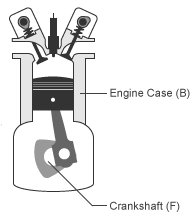
| B | Rotational conserving port representing the engine block |
| F | Rotational Conserving port representing the engine crankshaft |
| T | Physical signal input port specifying the normalized engine throttle level |
| P | Physical signal output port reporting the instantaneous engine power, in W |
| FC | Physical signal output port reporting the fuel consumption rate, in kg/s |
Port T accepts a signal with values in the range 0–1. The signal specifies the engine torque as a fraction of the maximum torque possible in steady state at fixed engine speed. The signal saturates at zero and one. Values below zero are interpreted as zero. Values above one are interpreted as one.
Port FC does not output data when the Fuel consumption
model parameter is set to No fuel
consumption.
Parameters
Engine Torque
The table shows how the visibility of some parameters depends on the option that you choose for other parameters. To learn how to read the table, see Parameter Dependencies.
Engine Torque Parameter Dependencies
| Engine Torque | ||
|---|---|---|
Model parameterization —
Choose | ||
| Normalized 3rd-order polynomial matched to peak power | Tabulated torque data | Tabulated power data |
Engine type — Choose
| Speed vector | |
Maximum power | Torque vector | |
Speed at maximum power | Interpolation
method — Choose | |
Maximum speed | ||
Stall speed | ||
- Model parameterization
Select how to model the engine. Choose between these options, each of which enable other parameters:
Normalized 3rd-order polynomial matched to peak power— Parametrize the engine with a power function controlled by power and speed characteristics. This is the default option.Tabulated torque data— Engine is parametrized by speed–torque table that you specify.Tabulated power data— Engine is parametrized by speed–power table that you specify.
- Engine type
Choose type of internal combustion engine. Choose between
Spark-ignition, the default option, andDiesel.Selecting
Normalized 3rd-order polynomial matched to peak powerfor the Model parameterization parameter exposes this parameter.For more information, see the Engine Torque Parameter Dependencies table.
- Maximum power
Maximum power Pmax that the engine can output. The default is
150kW.Selecting
Normalized 3rd-order polynomial matched to peak powerfor the Model parameterization parameter exposes this parameter.For more information, see the Engine Torque Parameter Dependencies table.
- Speed at maximum power
Engine speed Ω0 at which the engine is running at maximum power. The default is
4500rpm.Selecting
Normalized 3rd-order polynomial matched to peak powerfor the Model parameterization parameter exposes this parameter.For more information, see the Engine Torque Parameter Dependencies table.
- Maximum speed
Maximum speed Ωmax at which the engine can generate torque. The default is
6000rpm.During simulation, if Ω exceeds this maximum, the simulation stops with an error. The engine maximum speed Ωmax cannot exceed the engine speed at which the engine power becomes negative.
Selecting
Normalized 3rd-order polynomial matched to peak powerfor the Model parameterization parameter exposes this parameter.For more information, see the Engine Torque Parameter Dependencies table.
- Stall speed
Minimum speed Ωmin at which the engine can generate torque. The default is
500rpm.During simulation, if Ω falls below this minimum, the engine torque is blended to zero.
Selecting
Normalized 3rd-order polynomial matched to peak powerfor the Model parameterization parameter exposes this parameter.For more information, see the Engine Torque Parameter Dependencies table.
- Speed vector
Vector of values of the engine function's independent variable, the speed Ω. The default is
[500, 1000, 2000, 3000, 4000, 5000, 6000, 7000]rpm.The first and last speeds in the vector are interpreted as the stall speed and the maximum speed, respectively. If the speed falls below the stall speed, engine torque is blended to zero. If the speed exceeds the maximum speed, the simulation stops with an error.
Selecting
Tabulated torque dataorTabulated power datafor the Model parameterization parameter exposes this parameter.For more information, see the Engine Torque Parameter Dependencies table.
- Torque vector
Vector of values of the engine function's dependent variable, the torque τ. The default is
[380, 380, 380, 380, 350, 280, 200, 80]N*m.Selecting
Tabulated torque datafor the Model parameterization parameter exposes this parameter.For more information, see the Engine Torque Parameter Dependencies table.
- Power vector
Vector of values of the engine function's dependent variable, the power P. The default is
[20, 40, 78, 120, 145, 148, 125, 60]kW.Selecting
Tabulated power datafor the Model parameterization parameter exposes this parameter.For more information, see the Engine Torque Parameter Dependencies table.
- Interpolation method
Method to interpolate the engine speed–torque or speed–power function between discrete relative velocity values within the range of definition. Choose between
Linear, the default choice, andSmooth.Selecting
Tabulated torque dataorTabulated power datafor the Model parameterization parameter exposes this parameter.For more information, see the Engine Torque Parameter Dependencies table.
Dynamics
The table shows how the visibility of some parameters depends on the option that you choose for other parameters. To learn how to read the table, see Parameter Dependencies.
Dynamics Parameter Dependencies
| Dynamics | |
|---|---|
Inertia — Choose
| |
| No inertia | Specify inertia and initial velocity |
Engine inertia | |
Initial velocity | |
Time constant — Choose
| |
| No lag - Suitable for HIL simulation | Specify time constant and initial value |
Engine time constant | |
Initial normalized throttle | |
- Inertia
Select how to model the rotational inertia of the engine block. Choose between these options, each of which exposes other parameters:
No inertia— Engine crankshaft is modeled with no inertia. This option is the default.Specify inertia and initial velocity— Engine crankshaft is modeled with rotational inertia and initial angular velocity.
- Engine Inertia
Rotational inertia of the engine crankshaft. The default is
1kg*m^2.Selecting
Specify inertia and initial velocityfor the Inertia parameter exposes this parameter.For more information, see the Dynamics Parameter Dependencies table.
- Initial velocity
Initial angular velocity Ω(0) of the engine crankshaft. The default is
800rpm.Selecting
Specify inertia and initial velocityfor the Inertia parameter exposes this parameter.For more information, see the Dynamics Parameter Dependencies table.
- Time constant
Select how to model the time lag of the engine response. Choose between these options, each of which exposes other options:
No lag — Suitable for HIL simulation— Engine reacts with no time lag. This option is the default.Specify time constant and initial value— Engine reacts with a time lag.Selecting
Specify time constant and initial valueexposes other parameters.For more information, see the Dynamics Parameter Dependencies table.
- Engine time constant
Engine time lag. The default is
0.2s.Selecting
Specify time constant and initial valuefor the Time constant parameter exposes this parameter.For more information, see the Dynamics Parameter Dependencies table.
- Initial normalized throttle
Initial normalized engine throttle T(0), ranging between zero and one. The default is
0.Selecting
Specify time constant and initial valuefor the Time constant parameter exposes this parameter.For more information, see the Dynamics Parameter Dependencies table.
Limits
- Speed threshold
Width of the speed range over which the engine torque is blended to zero as Ω approaches the stall speed. The default is
100rpm.
Fuel Consumption
The table shows how the visibility of some parameters depends on the option that you choose for other parameters. To learn how to read the table, see Parameter Dependencies.
Fuel Consumption Parameter Dependencies
| Fuel Consumption | ||||
|---|---|---|---|---|
Fuel consumption model — Choose
No fuel
                    consumption
,
Constant per revolution,
Fuel consumption by speed and
torque, Brake specific fuel
consumption by speed and torque, or
Brake specific fuel consumption by speed and
brake mean effective pressure | ||||
| No fuel consumption | Constant per revolution | Fuel consumption by speed and torque | Brake specific fuel consumption by speed and torque | Brake specific fuel consumption by speed and brake mean effective pressure |
Fuel consumption per revolution | Displaced volume | |||
Revolutions per cycle | ||||
Speed vector | ||||
Torque vector | Brake mean effective pressure vector | |||
Fuel consumption table | Brake specific fuel consumption table | |||
Interpolation method —
Choose | ||||
- Fuel consumption model
Select a model for calculating engine-fuel consumption. Model parameterizations are compatible with standard industrial data. Choose between these options:
No fuel consumption— The default optionConstant per revolutionFuel consumption by speed and torqueBrake specific fuel consumption by speed and torqueBrake specific fuel consumption by speed and brake mean effective pressure
Some options expose other parameters. For more information, see the Fuel Consumption Parameter Dependencies table.
- No fuel consumption
The block does not calculate fuel consumption even when the FC port, which reports the fuel consumption rate, is connected to another block. Selecting this option increases simulation speed.
- Fuel consumption per revolution
Enter the volume of fuel consumed in one crankshaft revolution. The default is
25mg/rev.Selecting
Constant per revolutionfor the Fuel consumption model parameter exposes this parameter.For more information, see the Fuel Consumption Parameter Dependencies table.
- Displaced volume
Enter the volume displaced by a piston stroke. The default is
400cm^3.Selecting
Brake specific fuel consumption by speed and brake mean effective pressurefor the Fuel consumption model parameter exposes this parameter.For more information, see the Fuel Consumption Parameter Dependencies table.
- Revolutions per cycle
Enter the number of crankshaft revolutions in one combustion cycle — e.g.
2for a four-stroke engine, or1for a two-stroke engine. The default is2.Selecting
Brake specific fuel consumption by speed and brake mean effective pressurefor the Fuel consumption model parameter exposes this parameter.For more information, see the Fuel Consumption Parameter Dependencies table.
- Speed vector
Enter vector of engine speeds used in lookup table parameterizations. Vector size must match Torque vector size. The default is
[1000, 2000, 3000, 4000, 5000, 6000]rpm. SelectingFuel consumption by speed and torque,Brake specific fuel consumption by speed and torque, orBrake specific fuel consumption by speed and brake mean effective pressurefor the Fuel consumption model parameter exposes this parameter.For more information, see the Fuel Consumption Parameter Dependencies table.
- Torque vector
Enter vector of engine torques used in the lookup table parameterizations. Vector size must match Speed vector size. The default is
[0, 80, 160, 200, 240, 320, 360, 400]N*m. SelectingFuel consumption by speed and torqueorBrake specific fuel consumption by speed and torquefor the Fuel consumption model parameter exposes this parameter.For more information, see the Fuel Consumption Parameter Dependencies table.
- Fuel consumption table
Enter matrix with fuel consumption rates corresponding to engine speed and torque vectors. The number of rows must equal the number of elements in the Speed vector. The number of columns must equal the number of elements in the Torque vector. The default is
[.5, .9, 1.4, 1.6, 1.9, 2.7, 3.4, 4.4; 1, 1.7, 2.7, 3.1, 3.6, 5, 6, 7.4; 1.4, 2.7, 4, 4.8, 5.6, 7.5, 8.5, 10.5; 2, 3.6, 5.8, 6.7, 8, 10.4, 11.7, 13.3; 2.5, 4.8, 7.9, 9.4, 10.8, 14, 16.2, 18.6; 3.1, 6, 10.3, 11.9, 13.8, 18.4, 22, 26.5]g/s.Selecting
Fuel consumption by speed and torquefor the Fuel consumption model parameter exposes this parameter.For more information, see the Fuel Consumption Parameter Dependencies table.
- Brake mean effective pressure vector
Enter vector of brake mean effective pressure (BMEP) values. The default is
[0, 250, 500, 625, 750, 1000, 1150, 1250]kPa. The BMEP satisfies the expression:where:
T — Output torque
nc — Number of cycles per revolution
Vd — Cylinder displaced volume
Selecting
Brake specific fuel consumption by speed and brake mean effective pressurefor the Fuel consumption model parameter exposes this parameter.For more information, see the Fuel Consumption Parameter Dependencies table.
- Brake specific fuel consumption table
Selecting
Brake specific fuel consumption by speed and torqueorBrake specific fuel consumption by speed and brake mean effective pressurefor the Fuel consumption model parameter exposes this parameter.For more information, see the Fuel Consumption Parameter Dependencies table.
For the
Brake specific fuel consumption by speed and torquefuel model, enter the matrix with brake specific fuel consumption (BSFC) rates corresponding to engine speed and torque vectors. BSFC is the ratio of the fuel consumption rate to the output power. The number of rows must equal the number of elements in the Speed vector. The number of columns must equal the number of elements in the Torque vector.For the
Brake specific fuel consumption by speed and brake mean effective pressurefuel model, enter the matrix with brake specific fuel consumption (BSFC) rates corresponding to engine speed and brake mean effective pressure (BMEP) vectors. BSFC is the ratio of the fuel consumption rate to the output power. The number of rows must equal the number of elements in the Speed vector. The number of columns must equal the number of elements in the Brake mean effective pressure vector.For both fuel-consumption models, the default is
[410, 380, 300, 280, 270, 290, 320, 380; 410, 370, 290, 270, 260, 270, 285, 320; 415, 380, 290, 275, 265, 270, 270, 300; 420, 390, 310, 290, 285, 280, 280, 285; 430, 410, 340, 320, 310, 300, 310, 320; 450, 430, 370, 340, 330, 330, 350, 380]g/hr/kW.- Interpolation method
Select the interpolation method used to calculate fuel consumption at intermediate speed-torque values. Methods are
LinearandSmooth. Outside the data range, fuel consumption is held constant at the last value given in the lookup table. SelectingFuel consumption by speed and torque,Brake specific fuel consumption by speed and torque, orBrake specific fuel consumption by speed and brake mean effective pressurefor the Fuel consumption model parameter exposes this parameter.For more information, see the Fuel Consumption Parameter Dependencies table.
Speed Control
The table shows how the visibility of some parameters depends on the option that you choose for other parameters. To learn how to read the table, see Parameter Dependencies.
Speed Control Parameter Dependencies
| Speed Control | |
|---|---|
Idle speed control — Choose
| |
| Off | On |
Idle speed reference | |
Controller time constant | |
Redline control | |
Redline control — Choose
| |
| Off | On |
Redline speed | |
Redline time constant | |
Redline threshold speed | |
- Idle speed control
Select speed control model. The options are:
Off— Omit idle speed controller. Throttle input is used directly. This option is the default.On— Include idle speed controller to prevent engine stalling. This option exposes other parameters. For more information, see Idle Speed Controller Model.
- Idle speed reference
Enter the value of the speed reference below which speed increases, and above which speed decreases. The default is
1000rpm.Selecting
Onfor the Idle speed control parameter exposes this parameter.For more information, see the Speed Control Parameter Dependencies table.
- Controller time constant
Enter the value of the time constant associated with an increase or decrease of the controlled throttle. The constant value must be positive. The default is
1s.Selecting
Onfor the Idle speed control parameter exposes this parameter.For more information, see the Speed Control Parameter Dependencies table.
- Controller threshold speed
Parameter used to smooth the controlled throttle value when the engine’s rotational speed crosses the idle speed reference. For more information, see Idle Speed Controller Model. Large values decrease controller responsiveness. Small values increase computational cost. This parameter must be positive. The default is
1rpm.Selecting
Onfor the Idle speed control parameter exposes this parameter.For more information, see the Speed Control Parameter Dependencies table.
- Redline control
Select redline control model. Options include
OffandOn.Off— Omit redline controller. Throttle depends only on the idle speed controller. This option is the default.On— Include redline controller to prevent excessive speed. This option exposes other parameters.For more information, see the Speed Control Parameter Dependencies table.
- Redline speed
Enter the value of the speed reference above which the redline control activates. The default is
5000rpm.Selecting
Onfor the Redline control parameter exposes this parameter.For more information, see the Speed Control Parameter Dependencies table.
- Redline time constant
Enter the value of the time constant associated with an increase or decrease of the controlled throttle. The constant value must be positive. The default is
1s.Selecting
Onfor the Redline control parameter exposes this parameter.For more information, see the Speed Control Parameter Dependencies table.
- Redline threshold speed
Specify the width of the region around the redline speed where the controller goes from fully enabled to not enabled. The block uses this parameter for smoothing the controlled throttle value when the engine’s rotational speed crosses the redline speed reference. Large values decrease controller responsiveness. Small values increase computational cost. This parameter must be positive. The default is
1rpm.Selecting
Onfor the Redline control parameter exposes this parameter.For more information, see the Speed Control Parameter Dependencies table.
Real-Time Simulation
Hardware-in-the-Loop Simulation
For optimal simulation performance, set the Dynamics > Time Constant parameter to No time constant - Suitable for HIL
simulation.
Extended Capabilities
See Also
Simscape Blocks
Topics
- Complete Vehicle Model
- Adjust Model Fidelity
- Hydraulically-Actuated Driveline Clutch
- Vehicle with Dual Clutch Transmission
- Vehicle with Four-Speed Transmission
- Vehicle with Four-Wheel Drive
- Vehicle with Manual Transmission
- Prepare Simscape Driveline Models for Real-Time Simulation Using Simscape Checks
- Troubleshoot Engine Issues