Code Generation from a MATLAB Function Block
Counter Model Using the MATLAB Function block
In this tutorial, you construct and configure a simple model,
eml_hdl_incrementer_tut, and then generate VHDL® code from the model. eml_hdl_incrementer_tut
includes a MATLAB Function block that implements a simple fixed-point
counter function, incrementer. The incrementer
function is invoked once during each sample period of the model. The function
maintains a persistent variable count, which is either
incremented or reinitialized to a preset value (ctr_preset_val),
depending on the value passed in to the ctr_preset input of the
MATLAB Function block. The function returns the counter value
(counter) at the output of the MATLAB Function
block.
The MATLAB Function block resides in a subsystem,
DUT_eML_Block. The subsystem functions as the device under
test (DUT) from which you generate HDL code.
The root-level model drives the subsystem and includes Display and To Workspace blocks for use in simulation. (The Display and To Workspace blocks do not generate HDL code.)
Tip
If you do not want to construct the model step by step, or do not have time, you can open the completed model by entering the name at the command prompt:
eml_hdl_incrementer
After you open the model, save a copy of it to your local folder as
eml_hdl_incrementer_tut.
The Incrementer Function Code
The following code listing gives the complete incrementer
function definition:
function counter = incrementer(ctr_preset, ctr_preset_val)
% The function incrementer implements a preset counter that counts
% how many times this block is called.
%
% This example function shows how to model memory with persistent variables,
% using fimath settings suitable for HDL. It also demonstrates MATLAB
% operators and other language features that HDL Coder supports
% for code generation from Embedded MATLAB Function block.
%
% On the first call, the result 'counter' is initialized to zero.
% The result 'counter' saturates if called more than 2^14-1 times.
% If the input ctr_preset receives a nonzero value, the counter is
% set to a preset value passed in to the ctr_preset_val input.


persistent current_count;
if isempty(current_count)
    % zero the counter on first call only
    current_count = uint32(0);
end


counter = getfi(current_count);

if ctr_preset
    % set counter to preset value if input preset signal is nonzero
    counter = ctr_preset_val;
else
    % otherwise count up
    inc = counter + getfi(1);
    counter = getfi(inc);
end

% store counter value for next iteration
current_count = uint32(counter);

function hdl_fi = getfi(val)

nt = numerictype(0,14,0);
fm = hdlfimath;
hdl_fi = fi(val, nt, fm);
Setting Up
Before you begin building the example model, set up a working folder for your model and generated code.
Setting Up a folder
Start MATLAB®.
Create a folder named
eml_tut, for example:mkdir D:\work\eml_tutThe
eml_tutfolder stores the model you create, and also contains sub-folders and generated code. The location of the folder does not matter, except that it should not be within the MATLAB tree.Make the
eml_tutfolder your working folder, for example:cd D:\work\eml_tut
Creating the Model and Configuring General Model Settings
In this section, you create a model and set some parameters to values recommended
for HDL code generation hdlsetup command. The
hdlsetup command uses the set_param
function to set up models for HDL code generation quickly and consistently. See
Customize hdlsetup Function Based on Target Application for further
information about hdlsetup.
To set the model parameters:
Create a new model.
Save the model as
eml_hdl_incrementer_tut.At the MATLAB command prompt, type:
hdlsetup('eml_hdl_incrementer_tut');Open the Configuration Parameters dialog box.
Set the following Solver options, which are useful in simulating this model:
Fixed step size: 1
Stop time: 5
Click OK to save your changes and close the Configuration Parameters dialog box.
Save your model.
Adding a MATLAB Function Block to the Model
Open the Simulink® Library Browser. Then, select the Simulink/User-Defined Functions library.
Select the MATLAB Function block from the library window and add it to the model.

Change the block label from
MATLAB Functiontoeml_inc_block.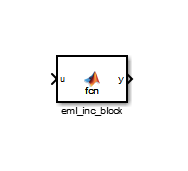
Save the model.
Close the Simulink Library Browser.
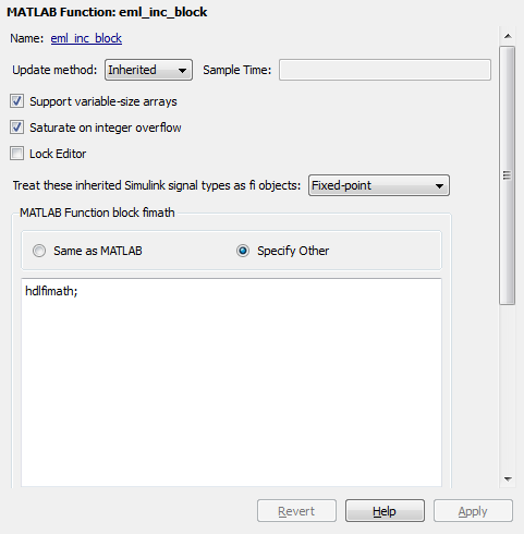
Set Fixed-Point Options for the MATLAB Function Block
This section describes how to set up the fimath specification
and other fixed-point options that are recommended for efficient HDL code generation
from the MATLAB Function block. The recommended settings are:
ProductModeproperty of thefimathspecification:'FullPrecision'SumModeproperty of thefimathspecification:'FullPrecision'Treat these inherited signal types as fi objects option:
Fixed-point(This is the default setting.)
Configure the options as follows:
Open the
eml_hdl_incrementer_tutmodel that you created in Adding a MATLAB Function Block to the Model.Double-click the MATLAB Function block to open it for editing. The MATLAB Function Block Editor appears.
Click Edit Data. The Ports and Data Manager dialog box opens, displaying the default
fimathspecification and other properties for the MATLAB Function block.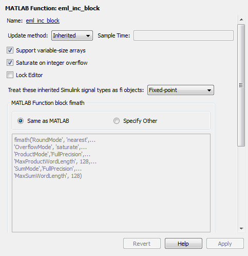
Select Specify Other. Selecting this option enables the MATLAB Function block fimath text entry field.
The
hdlfimathfunction is a utility that defines a FIMATH specification that is optimized for HDL code generation. Replace the default MATLAB Function block fimath specification with a call tohdlfimathas follows:hdlfimath;
Click Apply. The MATLAB Function block properties should now appear as shown in the following figure.
Close the Ports and Data Manager.
Save the model.
Programming the MATLAB Function Block
The next step is add code to the MATLAB Function block to define
the incrementer function, and then use diagnostics to check for
errors.
Open the
eml_hdl_incrementer_tutmodel that you created in Adding a MATLAB Function Block to the Model.Double-click the MATLAB Function block to open it for editing.
In the MATLAB Function Block Editor, delete the default code.
Copy the complete
incrementerfunction definition from the listing given in The Incrementer Function Code, and paste it into the editor.Save the model. Doing so updates the model window, redrawing the MATLAB Function block.
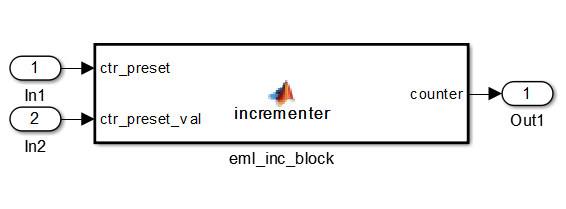
Changing the function header of the MATLAB Function block makes the following changes to the block icon:
The function name in the middle of the block changes to
incrementer.The arguments
ctr_presetandctr_preset_valappear as input ports to the block.The return value
counterappears as an output port from the block.
Resize the block to make the port labels more legible.

Save the model again.
Constructing and Connecting the DUT_eML_Block Subsystem
This section assumes that you have completed Programming the MATLAB Function Block without
encountering an error. In this section, you construct a subsystem containing the
incrementer function block, to be used as the device under
test (DUT) from which to generate HDL code. You then set the port data types and
connect the subsystem ports to the model.
Constructing the DUT_eML_Block Subsystem
Construct a subsystem containing the incrementer function
block as follows:
Click the
incrementerfunction block.On the Modeling tab of the Simulink Toolstrip, select Create Subsystem.
A subsystem, labeled
Subsystem, is created in the model window.Change the
Subsystemlabel toDUT_eML_Block.
Setting Port Data Types for the MATLAB Function Block
Double-click the subsystem to view its interior. As shown in the following figure, the subsystem contains the
incrementerfunction block, with input and output ports connected.Double-click the
incrementerfunction block to open the MATLAB Function Block Editor.In the editor, click Edit Data to open the Ports and Data Manager.
Select the
ctr_presetentry in the port list on the left. Click the button labeled >> to display the Data Type Assistant. Set Mode for this port toBuilt in. Set Data type toboolean. Click the button labeled << to close the Data Type Assistant. Click Apply.Select the
ctr_preset_valentry in the port list on the left. Click the button labeled >> to display the Data Type Assistant. Set Mode for this port toFixed point. Set Signedness toUnsigned. Set Word length to 14. Click the button labeled << to close the Data Type Assistant. Click Apply.Select the
counterentry in the port list on the left. Click the button labeled >> to display the Data Type Assistant. Verify that Mode for this port is set toInherit: Same as Simulink. Click the button labeled << to close the Data Type Assistant. Click Apply.Close the Ports and Data Manager dialog box and the MATLAB Function Block Editor.
Save the model and close the
DUT_eML_Blocksubsystem.
Connecting Subsystem Ports to the Model
Next, connect the ports of the DUT_eML_Block subsystem to
the model as follows:
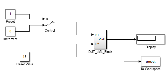
From the Sources library, add a Constant block to the model. Set the value of the Constant block to 1, and the Output data type to
boolean. Change the block label toPreset.Make a copy of the
PresetConstant block. Set its value to 0, and change its block label toIncrement.From the Signal Routing library, add a Manual Switch block to the model. Change its label to
Control. Connect its output to theIn1port of theDUT_eML_Blocksubsystem.Connect the
PresetConstant block to the upper input of theControlswitch block. Connect theIncrementConstant block to the lower input of theControlswitch block.Add a third Constant block to the model. Set the value of the Constant to 15, and the Output data type to
Inherit via back
                                propagation
. Change the block label toPreset Value.Connect the
Preset ValueConstant block to theIn2port of theDUT_eML_Blocksubsystem.From the Sinks library, add a Display block to the model. Connect it to the
Out1port of theDUT_eML_Blocksubsystem.From the Sinks library, add a To Workspace block to the model. Route the output signal from the
DUT_eML_Blocksubsystem to the To Workspace block.Save the model.
Checking the Function for Errors
Use the built-in diagnostics of MATLAB Function blocks to test for syntax errors:
Open the
eml_hdl_incrementer_tutmodel.Double-click the MATLAB Function block
incrementerto open it for editing.In the MATLAB Function Block Editor, select Build Model > Build to compile and build the MATLAB Function block code.
The build process displays some progress messages. These messages include some warnings, because the ports of the MATLAB Function block are not yet connected to signals. You can ignore these warnings.
The build process builds an S-function for use in simulation. The build process includes generation of C code for the S-function. The code generation messages you see during the build process refer to generation of C code, not HDL code generation.
When the build concludes without encountering an error, a message window appears indicating that parsing was successful. If errors are found, the Diagnostics Manager lists them. See the MATLAB Function block documentation for information on debugging MATLAB Function block build errors.
Compiling the Model and Displaying Port Data Types
In this section you enable the display of port data types and then compile the model. Model compilation verifies the model structure and settings, and updates the model display.
In the Debug tab of the Simulink Toolstrip, on the Information Overlays > Ports section, select Base data types.
Press Ctrl+D to compile and update the model. This triggers a rebuild of the code. After the model compiles, the block diagram updates to show the port data types.

Save the model.
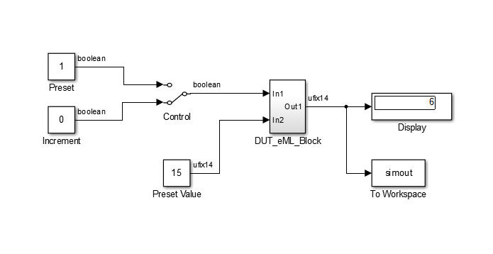
Simulating the eml_hdl_incrementer_tut Model
Start simulation. If required, the code rebuilds before the simulation starts.
After the simulation completes, the Display block shows the final output value
returned by the incrementer function block. For example, given a
Start time of 0, a Stop time of 5, and
a zero value at the ctr_preset port, the simulation returns a
value of 6:
You might want to experiment with the results of toggling the
Control switch, changing the Preset Value
constant, and changing the total simulation time. You might also want to examine the
workspace variable simout, which is bound to the To
Workspace block.
Generating HDL Code
In this section, you select the DUT_eML_Block subsystem for HDL
code generation, set basic code generation options, and then generate VHDL code for the subsystem.
Selecting the Subsystem for Code Generation
Select the DUT_eML_Block subsystem for code
generation:
Open the Configuration Parameters dialog box and click the HDL Code Generation pane.
Select
eml_hdl_incrementer_tut/DUT_eML_Blockfrom the Generate HDL for list.Click Apply.
Generating VHDL Code
In the Configuration Parameters dialog box, the top-level HDL Code Generation options should now be set as follows:
The Generate HDL for field specifies the
eml_hdl_incrementer_tut/DUT_eML_Blocksubsystem for code generation.The Language field specifies (by default) generation of VHDL code.
The Folder field specifies (by default) that the code generation target folder is a subfolder of your working folder, named
hdlsrc.
Before generating code, select Current Folder from the Layout menu in the MATLAB Command Window. This displays the Current Folder browser, which lets you easily access your working folder and the files that are generated within it.
To generate code:
Click the Generate button.
HDL Coder™ compiles the model before generating code. Depending on model display options (such as port data types), the appearance of the model might change after code generation.
As code generation proceeds, the coder displays progress messages. The process should complete with a message like the following:
### HDL Code Generation Complete.
The names of generated VHDL files in the progress messages are hyperlinked. After code generation completes, you can click these hyperlinks to view the files in the MATLAB Editor.
A folder icon for the
hdlsrcfolder is now visible in the Current Folder browser. To view generated code and script files, double-click thehdlsrcfolder icon.Observe that two VHDL files were generated. The structure of HDL code generated for MATLAB Function blocks is similar to the structure of code generated for Stateflow® charts and Digital Filter blocks. The VHDL files that were generated in the
hdlsrcfolder are:eml_inc_blk.vhd: VHDL code. This file contains entity and architecture code implementing the actual computations generated for the MATLAB Function block.DUT_eML_Block.vhd: VHDL code. This file contains an entity definition and RTL architecture that provide a black box interface to the code generated ineml_inc_blk.vhd.
The structure of these code files is analogous to the structure of the model, in which the
DUT_eML_Blocksubsystem provides an interface between the root model and theincrementerfunction in the MATLAB Function block.The other files generated in the
hdlsrcfolder are:DUT_eML_Block_compile.do: Mentor Graphics® ModelSim® compilation script (vcomcommand) to compile the VHDL code in the two.vhdfiles.DUT_eML_Block_synplify.tcl: Synplify® synthesis script.DUT_eML_Block_map.txt: Mapping file. This report file maps generated entities (or modules) to the subsystems that generated them (see Trace Code Using the Mapping File).
To view the generated VHDL code in the MATLAB Editor, double-click the
DUT_eML_Block.vhdoreml_inc_blk.vhdfile icons in the Current Folder browser.
See Also
Check for MATLAB Function block settings