Repeat an Algorithm Using a For Each Subsystem
If you repeat algorithms in a diagram by copying and pasting blocks and subsystems, maintaining the model can become difficult. Individual signal lines and subsystems can crowd the diagram, reducing readability and making simple changes difficult. Variables can also crowd workspaces, reducing model portability. A model can develop these efficiency issues as you add to the design over time.
To repeat an algorithm, you can iterate the algorithm over signals, subsystems, and parameters that are grouped into arrays and structures. This example shows how to convert an inefficiently complex repetitive algorithm into a compact form that is easier to manage.
Explore Example Model
Open the example model
ex_repeat_algorithm. The model creates about 30 variables in the base workspace.Inspect the subsystem Burner_1_Analysis. This subsystem executes an algorithm by using the base workspace variables as parameters in blocks such as Constant and Discrete-Time Integrator.
Inspect the subsystems Burner_2_Analysis and Burner_3_Analysis. All three subsystems execute the same algorithm but use different workspace variables to parameterize the blocks.
Inspect the three Analysis_Delay subsystems. These subsystems repeat a different algorithm from the one in the Analysis subsystems.
Return to the top level of the model. The Memory blocks delay the input signals before they enter the Analysis_Delay subsystems.
Look at the Data Import/Export pane of the Configuration Parameters dialog box. The model uses the variables
SensorsInputandtas simulation inputs.During simulation, each of the nine columns in the matrix variable
SensorsInputprovides input data for an Inport block at the top level of the model.
Reduce Signal Line Density with Buses
You can use buses to group related signals into a single structured signal, reducing line density and improving model readability.
Each subsystem in the example model requires three signal inputs. You can combine each group of three signals into a single bus.
You could modify all the subsystems in the example model to use buses. However, because some of the subsystems are identical, you can delete them and later replace them with For Each Subsystem blocks.
Open the Bus Editor.
buseditor
Create a bus type
SensorDatawith three signal elements:sensor1,sensor2, andsensor3.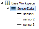
Delete the blocks as shown in the figure, leaving only the Burner_1_Sensor1 and Burner_1_Delay1 blocks as inputs to the two remaining subsystems.

On the Signal Attributes tab of the Burner_1_Sensor1 Inport block dialog box, set Data type to
Bus: SensorData.The output of the block is a bus that contains the three signal elements
sensor1,sensor2, andsensor3.Open the subsystem Burner_1_Analysis. Delete the signal output lines of the three Inport blocks. Delete the In2 and In3 Inport blocks.
Add a Bus Selector block to the right of the In1 Inport block. Connect the Inport block output to the Bus Selector block.
In the Bus Selector block dialog box, select the signals
sensor1,sensor2, andsensor3.
The Bus Selector block extracts the three signal elements from the input bus. Other blocks in the model can use the extracted signal elements.
In the subsystem, connect the blocks as shown.
In the subsystem Burner_1_Analysis_Delay, use a Bus Selector block to extract the signals in the bus. Use the same technique as you did in the subsystem Burner_1_Analysis.
Repeat an Algorithm
A For Each Subsystem block partitions an input signal and sequentially executes an algorithm on each partition. For example, if the input to the subsystem is an array of six signals, you can configure the subsystem to execute the same algorithm on each of the six signals.
You can use For Each subsystems to repeat an algorithm in an iterative fashion. This approach improves model readability and makes it easy to change the repeated algorithm .
Add two For Each Subsystem blocks to the model. Name one of the subsystems Burner_Analysis. Name the other subsystem Burner_Analysis_Delay.
Copy the contents of the subsystem Burner_1_Analysis into the subsystem Burner_Analysis. Before you paste the blocks, delete the Inport and Outport blocks in the For Each subsystem.
In the For Each block dialog box in the Burner_Analysis subsystem, select the check box to partition the input
In1.Copy the contents of the subsystem Burner_1_Analysis_Delay into the subsystem Burner_Analysis_Delay.
In the For Each block dialog box in the Burner_Analysis_Delay subsystem, select the check box to partition the input
In1.At the top level of the model, delete the subsystems Burner_1_Analysis and Burner_1_Analysis_Delay. Connect the new For Each Subsystem blocks in their place.
On the Signal Attributes tab of the Burner_1_Sensor1 Inport block dialog box, set Port dimensions to
3.The block output is a three-element array of buses. The For Each subsystems in the model repeat an algorithm for each of the three buses in the array.
Create a
Simulink.SimulationData.Datasetobject that the Inport block can use to import the simulation data. You can use this code to create the object and store it in the variableSensorsInput.% First, create an array of structures whose field values are % timeseries objects for i = 1:3 % Burner number % Sensor 1 eval(['tempInput(1,' num2str(i) ').sensor1 = ' ... 'timeseries(SensorsInput(:,' num2str(3*(i-1)+1) '),t);']) % Sensor 2 eval(['tempInput(1,' num2str(i) ').sensor2 = ' ... 'timeseries(SensorsInput(:,' num2str(3*(i-1)+2) '),t);']) % Sensor 3 eval(['tempInput(1,' num2str(i) ').sensor3 = ' ... 'timeseries(SensorsInput(:,' num2str(3*(i-1)+3) '),t);']) end % Create the Dataset object. SensorsInput = Simulink.SimulationData.Dataset; SensorsInput = addElement(SensorsInput,tempInput,'element1'); clear tempInput t i
The code first creates a variable
tempInputthat contains an array of three structures. Each structure has three fields that correspond to the signal elements in the bus typeSensorData, and each field stores a MATLAB®timeseriesobject. Eachtimeseriesobject stores one of the nine columns of data from the variableSensorsInput, which stores the simulation input data for each of the sensors.The code then overwrites
SensorsInputwith a newSimulink.SimulationData.Datasetobject and addstempInputas an element of the object.Set the Input configuration parameter to
SensorsInput.Since
SensorsInputprovides simulation input data in the form oftimeseriesobjects, you do not need to specify a variable that contains time data.Create an array of structures that initializes the remaining Memory block, and store the array in the variable
initForDelay. Specify the structure fields with the values of the existing initialization variables such asinitDelay_1_sensor1.for i = 1:3 % Burner number % Sensor 1 eval(['initForDelay(' num2str(i) ').sensor1 = ' ... 'initDelay_' num2str(i) '_sensor1;']) % Sensor 2 eval(['initForDelay(' num2str(i) ').sensor2 = ' ... 'initDelay_' num2str(i) '_sensor2;']) % Sensor 3 eval(['initForDelay(' num2str(i) ').sensor3 = ' ... 'initDelay_' num2str(i) '_sensor3;']) end
To view the contents of the new variable
initForDelay, double-click the variable name in the base workspace. The variable contains an array of three structures that each has three fields:sensor1,sensor2, andsensor3.
In the Memory block dialog box, set Initial condition to
initForDelay.The Memory block output is an array of buses that requires initialization. Each signal element in the array of buses acquires an initial value from the corresponding field in the array of structures.
Organize Parameters into Arrays of Structures
The base workspace contains many variables that the example model uses for block parameters. To reduce the number of workspace variables, package them into arrays of structures, and use the individual structure fields to specify block parameters.
A For Each Subsystem block can partition an array of values that you specify as a mask parameter. Each iteration of the subsystem uses a single partition of the array to specify block parameters. If you specify the parameter as an array of structures, each iteration of the subsystem can use one of the structures in the array.
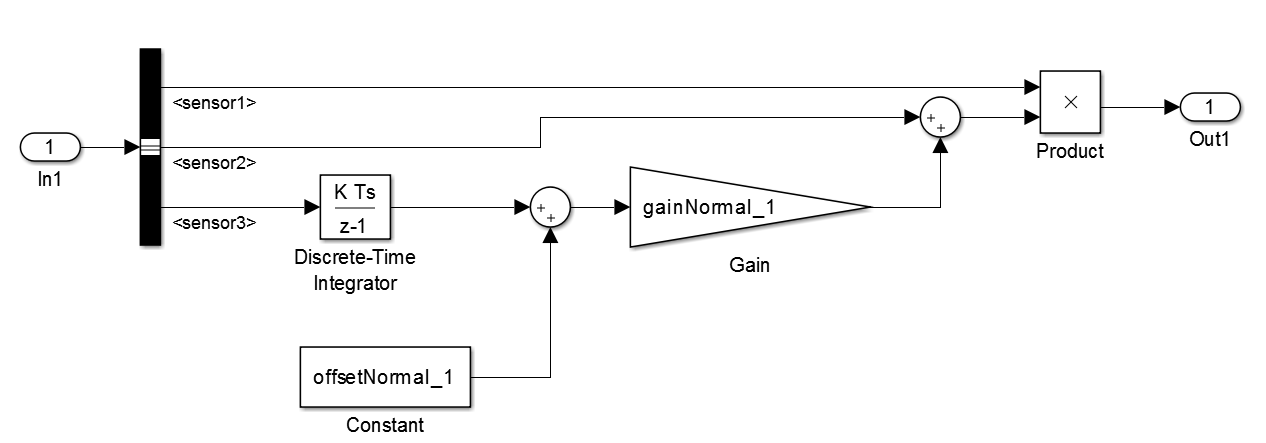
Create an array of structures that parameterizes the Burner_Analysis For Each subsystem, and store the array in the variable
paramsNormal. Specify the structure fields by using the values of existing parameter variables such asgainNormal_1,offsetNormal_1, andinitDelayed_1.for i = 1:3 eval(['paramsNormal(' num2str(i) ').gain = gainNormal_' num2str(i) ';']) eval(['paramsNormal(' num2str(i) ').offset = offsetNormal_' num2str(i) ';']) eval(['paramsNormal(' num2str(i) ').init = initNormal_' num2str(i) ';']) end
The variable contains an array of three structures that each has three fields:
gain,offset, andinit.In the model, right-click the Burner_Analysis For Each subsystem and select Mask > Create Mask.
On the Parameters & Dialog pane of the dialog box, under Parameter, click Edit. For the new mask parameter, set Prompt to
Parameter
                                structure
and Name toparamStruct. Click OK.In the mask for the Burner_Analysis subsystem, set Parameter structure to
paramsNormal.Open the subsystem. In the For Each block dialog box, on the Parameter Partition pane, select the check box to partition the parameter
paramStruct. Set Partition dimension to2.For the blocks in the subsystem, set these parameters.
Block Parameter Name Parameter Value Gain Gain paramStruct.gainDiscrete-Time Integrator Initial condition paramStruct.initConstant Constant value paramStruct.offsetCreate an array of structures that parameterizes the Burner_Analysis_Delay For Each subsystem, and store the array in the variable
paramsForDelay.for i = 1:3 eval(['paramsForDelay(' num2str(i) ').gain = gainDelayed_' num2str(i) ';']) eval(['paramsForDelay(' num2str(i) ').offset = offsetDelayed_' num2str(i) ';']) eval(['paramsForDelay(' num2str(i) ').init = initDelayed_' num2str(i) ';']) end
At the top level of the model, right-click the Burner_Analysis_Delay For Each subsystem and select Mask > Create Mask.
On the Parameters & Dialog pane of the dialog box, under Parameter, click Edit. For the new mask parameter, set Prompt to
Parameter
                                structure
and Name toparamStruct. Click OK.In the mask for the For Each Subsystem block, set Parameter structure to
paramsForDelay.Open the subsystem. In the For Each block dialog box, on the Parameter Partition pane, select the check box to partition the parameter
paramStruct. Set Partition dimension to2.For the blocks in the subsystem, set these parameters.
Block Parameter Name Parameter Value Gain Gain paramStruct.gainDiscrete-Time Integrator Initial condition paramStruct.initConstant Constant value paramStruct.offsetClear the unnecessary variables from the base workspace.
% Clear the old parameter variables that you replaced
% with arrays of structures
clear -regexp _

% Clear the iteration variables
clear i
The model requires few variables in the base workspace.
Inspect the Converted Model
To view the new signal and subsystem organization, update the diagram.
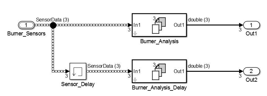
The model input is an array of three buses. The model uses two For Each subsystems to execute the two algorithms on each of the three buses in the input array.
In the base workspace, arrays of structures replace the many variables that the model used. Mathematically, the modified model behaves the same way it did when you started because the arrays of structures contain the values of all the old variables.
Tip
You can log nonbus signals in a For Each subsystem. However, you cannot use signal logging for buses or arrays of buses from within a For Each subsystem. Either use a Bus Selector block to select the bus element signals that you want to log or add an Outport block outside of the subsystem and then log that signal. For details, see Log Signals in For Each Subsystems.
Examples of Working with For Each Subsystems
Vectorize Algorithms Using For Each Subsystems
This example shows how to simplify modeling of vectorized algorithms. Using For Each Subsystem blocks simplifies a model where three input signals are filtered by three identical Transfer Fcn blocks. This example also shows how to add more control to the filters by changing their coefficients for each iteration of the subsystem.
This model uses identical Transfer Fcn blocks to independently process each element of the input sine wave signal. A Vector Concatenate block concatenates the resulting output signals. This repetitive process is graphically complex and difficult to maintain. Adding another element to the signal also requires significant reworking of the model.

You can simplify this model by replacing the repetitive operations with a single For Each Subsystem block.

The For Each subsystem block contains a For Each block and a model representing the algorithm of the three blocks it replaces by way of the Transfer Fcn block. The For Each block specifies how to partition the input signal vector into individual elements and how to concatenate the processed signals to form the output signal vector. Every block that has a state maintains a separate set of states for each input element processed during a given execution step.

For this example, the input signal is selected for partitioning. The
Partition Dimension and Partition
Width parameters on the For Each block are both set to
1 for the input.

You can scale up this approach to add more signals without having to change the model significantly. This approach is easily scalable and graphically simpler.
Model Parameter Variation Without Changing Model Structure. This example shows how to model parameter variation in an algorithm. It uses the For Each Subsystem partitioning model from the above example and creates different filters for each input signal while retaining model simplicity. An array of filter coefficients is fed to the For Each subsystem block as a mask parameter marked for partitioning. In each iteration of the For Each subsystem block, a partition of the filter coefficient array is fed to the Transfer Fcn block.
Open the model ex_ForEachSubsystem_Partitioning. Create a mask for the For Each Subsystem block and add an editable mask parameter. Set the name to
FilterCoeffsand the prompt toFilter Coefficient Matrix. For information on how to add a mask parameter, see Create a Simple Mask.
Open the For Each subsystem block. Inside the subsystem, open the For Each block dialog box.
In the Parameter Partition tab, select the check box next to the FilterCoeffs parameter to enable partitioning of this parameter. Keep the Partition Width and Partition Dimension parameters at their default value of 1.

Double-click the For Each Subsystem block and enter your filter coefficient matrix, having one row of filter coefficients for each input signal. For example, enter
[0.0284 0.2370 0.4692 0.2370 0.0284; -0.0651 0
                                        0.8698 0 -0.0651; 0.0284 -0.2370 0.4692 -0.2370
                                        0.0284]
to implement different fourth-order filters for each input signal.In the For Each Subsystem block, double-click the Transfer Fcn block and enter
FilterCoeffsfor the Denominator Coefficients parameter. This setting causes the block to get its coefficients from the mask parameter.
The For Each Subsystem block slices the input parameter into horizontal partitions of width 1, which is equivalent to one row of coefficients. The parameter of coefficients transforms from a single array

into three rows of parameters:

Improved Code Reuse Using For Each Subsystems. This example shows how you can improve code reuse when you have two or more identical For Each Subsystem blocks. Consider the following model, rtwdemo_foreachreuse.

The intent is for the three subsystems — Vector SS1, Vector SS2, and Vector SS3 — to apply the same processing to each scalar element of the vector signal at their respective inputs. Because these three subsystems perform the same processing, it is desirable for them to produce a single shared Output (and Update) function for all three subsystems in the code generated for this model. For example, the Vector SS3 subsystem contains the these blocks.

To generate a single shared function for the three subsystems, the
configuration of the partitioning they perform on their input signals must
be the same. For Vector SS1 and Vector SS3, this configuration is
straightforward because you can set the partition dimension and width to 1.
However, in order for Vector SS2 to also partition its input signal along
dimension 1, you must insert a Math Function block to
transpose the 1-by-8 row vector into an 8-by-1 column vector. You can then
convert the output of the subsystem back to a 1-by-8 row vector using a
second Math Function block set to the transpose
operator.
If you press Ctrl+B to generate code, the resulting code uses a single output function. This function is shared by all three For Each Subsystem instances.
/*
 * Output and update for iterator system:
 *    '<Root>/Vector SS1'
 *    '<Root>/Vector SS2'
 *    '<Root>/Vector SS3'
 */
void VectorProcessing(int32_T NumIters, const real_T rtu_In1[],
                      real_T rty_Out1[],
                      rtDW_VectorProcessing *localDW)
The function has an input parameter NumIters that
indicates the number of independent scalars that each For Each
Subsystem is to processes. This function is called three times
with the parameter NumIters set to 10, 8, and 7,
respectively.
The remaining two subsystems in this model show how reusable code can also be generated for matrix signals that are processed using the For Each Subsystem block. Again, pressing Ctrl+B to generate the code provides code reuse of a single function.