Separation of Code Definitions from Model-Specific Data and Function Configurations
By using the Embedded Coder Dictionary, you can define specifications that control data and functions in the generated code. You create custom specifications as code interface definitions, such as storage classes, memory sections, and function customization templates. To configure your model to use the definitions, map data items and functions in the model to the definitions.
Using an Embedded Coder Dictionary to specify your code, you can:
Create, store, and maintain the specifications for your generated code in one place.
Apply code definitions in the default mapping for your model.
Configure the code for many different elements throughout your model.
Choose how to apply your definitions with flexibility.
Configure the generated code for multiple models.
Use one model to generate code that is configured differently for different computing platforms.
Manage Code Specifications in One Location
When you create code definitions in an Embedded Coder Dictionary, you can manage the specifications for your generated code in one place. You do not need to specify your code customizations on each individual data item or function that you want to configure. By specifying your code in the Embedded Coder Dictionary, you can:
View and compare code definitions and their properties.
Find and fix code specifications that do not conform to requirements.
Change many code definitions quickly when software interface standards change.
Apply Definitions to Model Elements with Flexibility
Storing your code definitions in a dictionary gives you flexibility in applying the definitions to your model because the code definitions in a dictionary are separate from the elements in your model. Configure data elements and functions in your model by mapping them to code definitions. When you map an item to a code definition, the code generated for that item reflects the specifications in your code definition. To map model elements to code definitions, use the Code Mappings Editor. You can apply a code definition to one model element or to many model elements.
To configure many elements of the same type to use the same code definition, specify the definition in the default mapping. When you map a category of data elements or functions to a code definition, items in that category use the code definition by default for generating code. For example, if you want the input ports in your model to generate code that reads data from a specific file, define the data specifications in a storage class definition. Then, map the input ports data category to your storage class. By default, the input ports of the model generate code that reads data according to the specifications in your definition.
To configure an individual item to generate code according to its own specifications, map the item to its own code definition. If the item is in a category for which you have already specified a default mapping, the mapping for the individual item overrides the default mapping. The default and individual mappings enable you to configure many items in your model at once with the flexibility to configure items individually.
Generate Standardized Code from Multiple Models
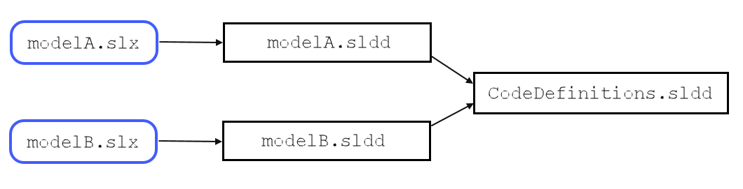
Separating code definitions from your model means that you can standardize the code generated from many models by sharing one set of code definitions. Because the definitions in your Embedded Coder Dictionary are separate from your model elements, you can share the definitions by storing the Embedded Coder Dictionary in a Simulink data dictionary outside of your model. The figure shows an example of two models sharing a dictionary. In the figure:
modelA.slxandmodelB.slxare separate models that generate code.Each model is linked to a Simulink® data dictionary, in this case, the dictionaries are
modelA.slddandmodelB.sldd.The separate Simulink data dictionary,
CodeDefinitions.sldd, contains the code interface definitions.The dictionaries for the models,
modelA.slddandmodelB.sldd, reference the dictionaryCodeDefinitions.sldd.For
modelAandmodelB, categories of model elements are mapped to the code definitions inCodeDefinitions.sldd. Both models generate code that reflects the specifications in the definitions.
To store your code definitions in a shared Simulink data dictionary:
Create a standalone Simulink data dictionary. In this dictionary, create code definitions to share with multiple models.
From each model with which you want to share the code definitions, create and link a Simulink data dictionary for model-specific design data.
From each model-specific data dictionary, reference the dictionary that contains the shared code definitions.
For the models that are linked to the dictionary, you can configure the default
mapping. In the shared Embedded Coder Dictionary, such as
CodeDefinitions.sldd, you can set the dictionary
default code definition for a category of model data or functions.
Models that are linked to the dictionary use the definition by default to generate
code for the associated category of data or functions. You can apply code interface
definitions to your linked models by default without modifying the individual
models.
You can still configure a linked model to use definitions that are different from the dictionary defaults. In the linked model, configure the default mapping and the individual mapping by using definitions that the model has access to, including definitions in the shared dictionary.
Generate Code for Different Platforms
By separating code definitions from your design data, you can generate code for different platforms from the same model or model hierarchy. For each platform:
Maintain a dictionary of code definitions that specify code interface behavior for the platform.
The models map model elements to definitions in the dictionary for the platform.
When you specify the associated system target file, the models use the mapping for the platform.
For example, you can share an Embedded Coder Dictionary with your models for an embedded real-time (ERT) target platform. For each of the models, maintain a separate AUTOSAR dictionary with definitions for an AUTOSAR platform. To configure the models for the ERT platform:
Specify an ERT-based system target file for the models.
Create code interface definitions in the shared Embedded Coder Dictionary.
For each model, in the Code Mappings editor, map categories of model elements and individual model elements to definitions in the Embedded Coder Dictionary.
When you specify the ERT-based system target file, the models use this code mapping.
To configure the models for the AUTOSAR code generation target:
Specify an AUTOSAR-based system target file.
Create code definitions in the AUTOSAR dictionaries.
In the Code Mappings editor, map model elements and categories to the definitions in the AUTOSAR dictionary.
When you specify the AUTOSAR-based system target file, the models use the AUTOSAR code mapping.
To generate code for either platform, specify the system target file. The code mapping for the model is updated to reflect the mapping and definitions that you specified for that platform.