Digital Up-Converter
Interpolate digital signal and translate it from baseband to Intermediate Frequency (IF) band
Library
Signal Operations
dspsigops

Description
The Digital Up-Converter (DUC) block converts a complex digital baseband signal to a real passband signal.
The DUC block upsamples the input signal using a cascade of three interpolation filters. The block frequency upconverts the upsampled signal by multiplying it by the specified center frequency of the output signal. This block designs the interpolation filters according to the filter parameters that you set in the block dialog.
Structure
This block brings the capabilities of dsp.DigitalUpConverter
System object™ to the Simulink® environment.
The DUC block consists of a FIR interpolator, a CIC compensator, and a CIC interpolator. You can bypass the FIR interpolator, depending on how you set the DUC block parameters.

For more information on the structure that the DUC block uses, including the flow of
fixed-point input, see the Construction section in
dsp.DigitalUpConverter.
Dialog Box
Main Tab

- Interpolation factor
Interpolation factor, specified as a positive integer scalar, or as a 1-by-2 or 1-by-3 vector of positive integers. The default is
100.When you set this parameter to a scalar, the block chooses the interpolation factors for each of the three filtering stages.
When you set this parameter to a 1-by-2 vector, the block bypasses the first filter stage and sets the interpolation factor of the second and third filtering stages to the values in the first and second vector elements, respectively. Both elements of the Interpolation factor must be greater than
1.When you set this parameter to a 1-by-3 vector, the ith element of the vector specifies the interpolation factor for the ith filtering stage. The second and third elements of Interpolation factor must be greater than
1, and the first element must be1or2.- Minimum order filter design
When you select this check box, the block designs filters with the minimum order that meets the requirements specified in these parameters:
Passband ripple of cascade response (dB)
Stopband attenuation of cascade response (dB)
Two sided bandwidth of input signal (Hz)
Source of stopband frequency
Stopband frequency (Hz)
When you clear this check box, the block designs filters with orders that you specify in Order of first filter stage, Order of CIC compensation filter stage, and Number of sections of CIC interpolator. The filter designs meet the passband and stopband frequency specifications that you set in Two sided bandwidth of input signal (Hz), Source of stopband frequency, and Stopband frequency (Hz). By default, this check box is selected.
- Order of first filter stage
Order of the first filter stage, specified as an even positive integer scalar. When you specify Interpolation factor as a 1-by-2 vector, the block ignores the value of Order of first filter stage because the block bypasses the first filter stage. This parameter applies when you clear the Minimum order filter design check box. The default is
10.- Order of CIC compensation filter stage
Order of the CIC compensation filter stage, specified as a positive integer scalar. This parameter applies when you clear the Minimum order filter design check box. The default is
12.- Number of sections of CIC interpolator
Number of sections in the CIC interpolator, specified as a positive integer scalar. This parameter applies when you clear the Minimum order filter design check box. The default is
3.- Two sided bandwidth of input signal (Hz)
Two sided bandwidth of the input signal, specified as a positive integer scalar. The block sets the passband frequency of the cascade of filters to half the value that you specify in this parameter. The default is 200 kHz.
- Source of stopband frequency
Source of the stopband frequency, specified as
AutoorProperty. The default isAuto.When you set this parameter to
Auto, the block places the cutoff frequency of the cascade filter response at approximately Fc = SampleRate/2 Hz, and computes the stopband frequency as Fstop = Fc + TW/2. SampleRate is computed as1/ Ts, where Ts is the sample time of the input signal. TW is the transition bandwidth of the cascade response, computed as 2×(Fc–Fp), and the passband frequency, Fp, equals Bandwidth/2.When you set this parameter to
Property, specify the source in Stopband frequency (Hz).- Stopband frequency (Hz)
Stopband frequency, specified as a double-precision positive scalar. This parameter applies when you set the Source of stopband frequency to
Property. The default is150kHz.- Passband ripple of cascade response (dB)
Passband ripple of the cascade response, specified as a double-precision positive scalar. When you select the Minimum order filter design, the block designs the filters so that the cascade response meets the passband ripple that you specify in Passband ripple of cascade response (dB). This parameter applies when you select the Minimum order filter design check box. The default is
0.1dB.- Stopband attenuation of cascade response (dB)
Stopband attenuation of the cascade response, specified as a double-precision positive scalar. When you select the Minimum order filter design check box, the block designs the filters so that the cascade response meets the stopband attenuation that you specify in Stopband attenuation of cascade response (dB). This parameter applies when you select the Minimum order filter design check box. The default is
60dB.- Type of oscillator
Oscillator type, specified as one of the following:
Sine wave(default) — The block frequency upconverts the output of the interpolation filter cascade using a complex exponential signal obtained from samples of a sinusoidal trigonometric function.NCO— The block performs frequency up conversion with a complex exponential obtained using a numerically controlled oscillator (NCO).
- Center frequency of output signal (Hz)
Center frequency of the output signal, specified as a double-precision positive scalar. The value of this parameter must be less than or equal to half the product of the SampleRate times the total interpolation factor. SampleRate is computed as
1/ Ts, where Ts is the sample time of the input signal. The block up converts the input signal so that the output spectrum centers at the frequency you specify in Center frequency of output signal (Hz). The default is14MHz.- Number of NCO accumulator bits
Number of NCO accumulator bits, specified as an integer scalar in the range
[1 128]. This parameter applies when you set Type of oscillator toNCO. The default is16.- Number of NCO quantized accumulator
Number of NCO quantized accumulator bits, specified as an integer scalar in the range
[1 128]. This value must be less than the value you specify in Number of NCO accumulator bits. This parameter applies when you set Type of oscillator toNCO. The default is12.- Dither control for NCO
When you select this check box, a number of dither bits specified in Number of NCO dither bits applies dither to the NCO signal. This parameter applies when you set Type of oscillator to
NCO. By default, this check box is selected.- Number of NCO dither bits
Number of NCO dither bits, specified as an integer scalar smaller than the number of accumulator bits that you specify in Number of NCO accumulator bits. This parameter applies when you set Type of oscillator to
NCOand select the Dither control for NCO. The default is4.- Inherit sample rate from input
When you select this check box, sample rate is computed as
N/ Ts, where N is the frame size of the input signal, and Ts is the sample time of the input signal. When you clear this check box, the block’s sample rate is the value specified in Input sample rate (Hz). By default, this check box is selected.- Input sample rate
Input sample rate, specified as a positive scalar. The value of this parameter multiplied by the total interpolation factor must be greater than or equal to twice the value of the Center frequency of output signal (Hz). The default is
30MHz. This parameter applies when you clear the Inherit sample rate from input check box.- View Filter Response
Opens the Filter Visualization Tool FVTool and displays the magnitude/phase response of each stage as well as the cascade of stages in the Digital Up-Converter. The response is based on the block dialog box parameters. Changes made to these parameters update FVTool.

To update the magnitude response while FVTool is running, modify the dialog box parameters and click Apply.
- Simulate using
Type of simulation to run. You can set this parameter to:
Code generation(default)Simulate model using generated C code. The first time you run a simulation, Simulink generates C code for the block. The C code is reused for subsequent simulations, as long as the model does not change. This option requires additional startup time but provides faster simulation speed than
Interpreted execution.Interpreted executionSimulate model using the MATLAB® interpreter. This option shortens startup time but has slower simulation speed than
Code
                                        generation
.
Data Types Tab
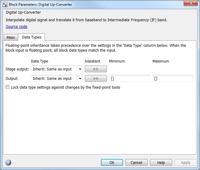
- Stage output
Data type of the output of the first, second, and third filter stages. You can set this parameter to:
Inherit: Same as input(default) — The block inherits the Stage output from the input signal.fixdt([],16,0)— Fixed-point data type with binary point scaling. Specify the sign mode of this data type as[]ortrue.An expression that evaluates to a data type, for example,
numerictype([],16,15). Specify the sign mode of this data type as[]ortrue.
The block casts the data at the output of each filter stage according to the value you set in this parameter. For the CIC stage, the casting is done after the signal has been scaled by the normalization factor.
Click the Show data type assistant button
 to display the data type assistant,
which helps you set the stage output parameter.
to display the data type assistant,
which helps you set the stage output parameter.See Specify Data Types Using Data Type Assistant (Simulink) for more information.
- Output
Data type of the block output. You can set this parameter to:
Inherit: Same as input(default) — The block Inherits the output datatype from the input.fixdt([],16,0)— Fixed-point data type with binary point scaling. Specify the sign mode of this data type as[]ortrue.An expression that evaluates to a data type, for example,
numerictype([],16,15). Specify the sign mode of this data type as[]ortrue.
Click the Show data type assistant button
to display the data type assistant,
which helps you set the Output parameter.See Specify Data Types Using Data Type Assistant (Simulink) for more information.
- Minimum
Minimum value of the block output. The default value is
[](unspecified). Simulink software uses this value to perform:Simulation range checking (see Specify Signal Ranges (Simulink))
Automatic scaling of fixed-point data types
- Maximum
Maximum value of the block output. The default value is
[](unspecified). Simulink software uses this value to perform:Simulation range checking (see Specify Signal Ranges (Simulink))
Automatic scaling of fixed-point data types
- Lock data type settings against changes by the fixed-point tools
Select this parameter to prevent the fixed-point tools from overriding the data types you specify on the block mask.
Supported Data Types
| Port | Supported Data Types |
|---|---|
Input |
|
Output |
|