connect
Block diagram interconnections of dynamic systems
Syntax
sysc = connect(sys1,...,sysN,inputs,outputs)

sysc = connect(sys1,...,sysN,inputs,outputs,APs)

sysc = connect(blksys,connections,inputs,outputs)

sysc = connect(___,opts)
Description
sysc = connect(sys1,...,sysN,inputs,outputs)sys1,...,sysN based
on signal names. The block diagram elements sys1,...,sysN are dynamic
system models. These models can include summing junctions
that you create using sumblk.
The connect command interconnects the block diagram
elements by matching the input and output signals that you specify
in the InputName and OutputName properties
of sys1,...,sysN. The aggregate model sysc is
a dynamic system model having inputs and outputs specified by inputs and outputs respectively.
sysc = connect(sys1,...,sysN,inputs,outputs,APs)AnalysisPoint at every
signal location specified in APs. Use analysis
points to mark locations of interest which are internal signals in
the aggregate model. For instance, a location at which you want to
extract a loop transfer function or measure the stability margins
is a location of interest.
sysc = connect(blksys,connections,inputs,outputs)sysc out
of an aggregate, unconnected model blksys. The
matrix connections specifies how the outputs
and inputs of blksys interconnect. For index-based
interconnections, inputs and outputs are
index vectors that specify which inputs and outputs of blksys are
the external inputs and outputs of sysc. This
syntax can be convenient when you do not want to assign names to all
inputs and outputs of all models to connect. However, in general,
it is easier to keep track of named signals.
sysc = connect(___,opts)opts with
the input arguments of any of the previous syntaxes.
Input Arguments
|
Dynamic
system models that correspond to the elements of your block
diagram. For example, the elements of your block diagram can include
one or more |
|
For name-based interconnection, a character vector or cell array
of character vectors that specify the inputs of the aggregate model |
|
For name-based interconnection, a character vector or cell array
of character vectors that specify the outputs of the aggregate model |
|
Locations (internal signals) of interest in the aggregate model,
specified as a character vector or cell array of character vectors,
such as |
|
Unconnected aggregate model. To obtain blksys = append(C,G,S) |
|
Matrix that specifies the connections and summing junctions
of the block diagram. Each row of [3 2 0 0] specifies that [7 2 -15 6] indicates that If you do not specify any connection for a particular input
or output, |
|
Additional options for interconnection, specified as an options
set that you create with |
Output Arguments
|
Interconnected system, returned as either a state-space model or frequency-response model. The type of model returned depends on the input models. For example:
By default, opt = connectOptions('Simplify',false); sysc = connect(sys1,sys2,sys3,'r','y',opt); |
Examples
SISO Feedback Loop
Create an aggregate model of the following block diagram from r to y.
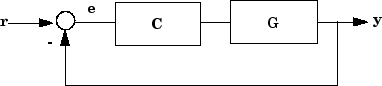
Create C and G, and name
the inputs and outputs.
C = pid(2,1);
C.u = 'e';
C.y = 'u';
G = zpk([],[-1,-1],1);
G.u = 'u';
G.y = 'y';
The notations C.u and C.y are
shorthand expressions equivalent to C.InputName and C.OutputName,
respectively. For example, entering C.u = 'e' is
equivalent to entering C.InputName = 'e'. The command
sets the InputName property of C to
the value 'e'.
Create the summing junction.
Sum = sumblk('e = r - y');
Combine C, G, and the
summing junction to create the aggregate model from r to y.
T = connect(G,C,Sum,'r','y');
connect automatically joins inputs and
outputs with matching names.
MIMO Feedback Loop
Create the control system of the previous example where G and C are
both 2-input, 2-output models.
C = [pid(2,1),0;0,pid(5,6)];
C.InputName = 'e';
C.OutputName = 'u';
G = ss(-1,[1,2],[1;-1],0);
G.InputName = 'u';
G.OutputName = 'y';
When you specify single names for vector-valued signals, the
software automatically performs vector expansion of the signal names.
For example, examine the names of the inputs to C.
C.InputName
ans =

    'e(1)'
    'e(2)'
Create a 2-input, 2-output summing junction.
Sum = sumblk('e = r-y',2);sumblk also performs
vector expansion of the signal names.
Interconnect the models to obtain the closed-loop system.
T = connect(G,C,Sum,'r','y');
The block diagram elements G, C,
and Sum are all 2-input, 2-output models. Therefore, connect performs
the same vector expansion. connect selects all
entries of the two-input signals 'r' and 'y' as
inputs and outputs to T, respectively. For example,
examine the input names of T.
T.InputName
ans =

    'r(1)'
    'r(2)'
Feedback Loop With Analysis Point Inserted by connect
Create a model of the following block diagram from r to y. Insert an analysis point at an internal location, u.

Create C and G, and name the inputs and outputs.
C = pid(2,1);
C.InputName = 'e';
C.OutputName = 'u';
G = zpk([],[-1,-1],1);
G.InputName = 'u';
G.OutputName = 'y';
Create the summing junction.
Sum = sumblk('e = r - y');Combine C, G, and the summing junction to create the aggregate model, with an analysis point at u.
T = connect(G,C,Sum,'r','y','u')
T =

  Generalized continuous-time state-space model with 1 outputs, 1 inputs, 3 states, and the following blocks:
    AnalysisPoints_: Analysis point, 1 channels, 1 occurrences.

Type "ss(T)" to see the current value, "get(T)" to see all properties, and "T.Blocks" to interact with the blocks.
The resulting T is a genss model. The connect command creates the AnalysisPoint block, AnalysisPoints_, and inserts it into T. To see the name of the analysis point channel in AnalysisPoints_, use getPoints.
getPoints(T)
ans = 1x1 cell array
    {'u'}
The analysis point channel is named 'u'. You can use this analysis point to extract system responses. For example, the following commands extract the open-loop transfer at u and the closed-loop response at y to a disturbance injected at u.
L = getLoopTransfer(T,'u',-1);
Tuy = getIOTransfer(T,'u','y');
T is equivalent to the following block diagram, where AP_u designates the AnalysisPoint block AnalysisPoints_ with channel name u.

Index-Based Interconnection
Create an aggregate model of the following block diagram from r to y using
index-based interconnection.
Create C, G, and the unconnected
aggregate model blksys.
C = pid(2,1);
G = zpk([],[-1,-1],1);
blksys = append(C,G);
The inputs u(1),u(2) of blksys correspond
to the inputs of C and G, respectively.
The outputs w(1),w(2) of blksys correspond
to the outputs of C and G, respectively.
Create the matrix connections, which specifies
which outputs of blksys connect to which inputs
of blksys.
connections = [2 1; 1 -2];
The first row indicates that w(1) connects
to u(2); in other words, that the output of C connects
to the input of G. The second row indicates that -w(2) connects
to u(1); in other words, that the negative of the
output of G connects to the input of C.
Create the connected aggregate model from r to y.
T = connect(blksys,connections,1,2)
The last two arguments specify the external inputs and outputs
in terms of the indices of blksys. The argument 1 specifies
that the external input connects to u(1). The last
argument, 2, specifies that the external output
connects from w(2).
See Also
AnalysisPoint | append | connectOptions | feedback | lft | parallel | series | sumblk