Create a Simple Mask
You can mask a block interactively by using the Mask Editor or mask it programmatically. This example describes how to mask a block by using the Mask Editor. To mask a block programmatically, see Control Masks Programmatically.
For masking examples, see Simulink Masking Examples.
Step 1: Open Mask Editor
Open the model in which you want to mask a block. For example, open
subsystem_example.This model contains a Subsystem block that models the equation for a line:
y = mx + b.Select the Subsystem block and on the Subsystem tab, in the Mask group,click Create Mask.

Step 2: Define the Mask
The Mask Editor contains four tabs that enable you to define the block mask and customize the dialog box for the mask.
For detailed information on each pane, see Mask Editor Overview.
Icon & Ports Tab
Use this tab to create an icon for the block mask. You can use the Options pane on the left to specify icon properties and icon visibility.
Add an image to the block mask.
In the Block frame drop-down box, select Visible.
In the Icon transparency drop-down box, select Opaque.
In the Icon units drop-down box, select Autoscale.
To restrict the icon rotation, select Fixed from the Icon rotation list.
In the Icon drawing commands text box, type,
x = [0 0.5 1 1.5];y = [0 0.5 1 1.5];
% An example to defines the variables x and y
plot(y,x) % Command to plot the graph
For more information on drawing command syntax, see Icon drawing commands.
To save the changes, click Apply. To preview the block mask icon without exiting the Mask Editor, click Preview

Note
For detailed information, see Icon & Ports Pane.
You can create static or dynamic block mask icons. For more information, see Draw Mask Icon and slexMaskDisplayAndInitializationExample.
Parameters & Dialog Tab
Use this tab to add controls like parameters, displays, and action items to the mask dialog box.
To add Edit boxes to the block mask.
In the left pane, under Parameter, click Edit twice to add two new rows in the Dialog box pane.
Type
SlopeandInterceptin the Prompt column for the two Edit parameters. The value that you enter in Prompt column appears on the mask dialog box. Similarly, typemandbin the Name column. The value you enter in Name column is the mask parameter name. The mask parameter name must be a valid MATLAB® name.In the right pane, under Property editor, provide values in the Properties, Dialog, and Layout sections.
Click Apply.

To preview the mask dialog box without exiting the Mask Editor, click Preview.
For detailed information, see Parameters & Dialog Pane.
Note
A Simulink® mask parameter cannot reference another parameter on the same mask.
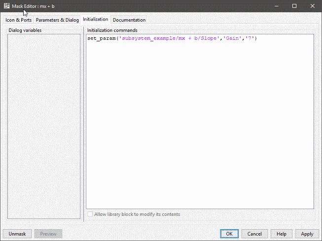
Initialization Tab
Use this pane to specify MATLAB code to control the mask parameters. For example,you can provide a predefined value for a mask parameter.
Consider the equation y = mx + b in the example. To set the value
of the child block corresponding to 'm', you can use the set_param
function in the initialization pane.

Note
For detailed information, see Initialization Pane.
Documentation Tab
Use this tab to add a name, description, and additional information for the mask.
The Documentation tab contains these fields:
Type: You can add a name for the block mask in this box. The mask name appears on top of the mask dialog box. You cannot add new lines.
Description: You can add a description for the block mask in this box. By default, the description is displayed below the mask name, and it can contain new lines and spaces.
Help. You can add additional information for the block mask in this box. You click Help on the mask dialog box, this information is displayed. You can use plain text, HTML and graphics, URLs, and
weborevalcommands to add information in the Help field.After you have added information in the Mask Editor, click Apply or OK.
The block is now masked.

Note
For detailed information, see Documentation Pane.
Step 3: Operate on Mask
You can preview the mask and choose to unmask the block or edit the block mask.
Double-click the masked block.

The mask dialog box appears.
Type values in the
SlopeandInterceptboxes of the mask dialog box. To view the output, simulate the model.Click OK.
To edit the mask definition, select the subsystem block and click Edit Mask from the Subsystem tab in the Toolstrip. For more information, see Manage Existing Masks.
Select the masked block and on the Subsystem Block tab, in the Mask group, click Look Under Mask to view:
The blocks inside the masked subsystem
The built-in block dialog box of a masked block
The base mask dialog box of a linked masked block