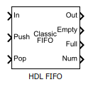
HDL FIFO
Stores sequence of input samples in first in, first out (FIFO) register
- Library:
HDL Coder / HDL RAMs
Description
The HDL FIFO block stores a sequence of input samples in a first in, first out (FIFO) register. The data written first into the FIFO register comes out first. The block implementation resembles the FIFO unit in hardware platforms in terms of functionality and behavior.
Ports
Input
Output
Parameters
Algorithms
FIFO Write Operation
This figure displays the FIFO write operation. The Push input port acts as the enable signal for the write operation. This signal is denoted by the write_en signal in the figure.
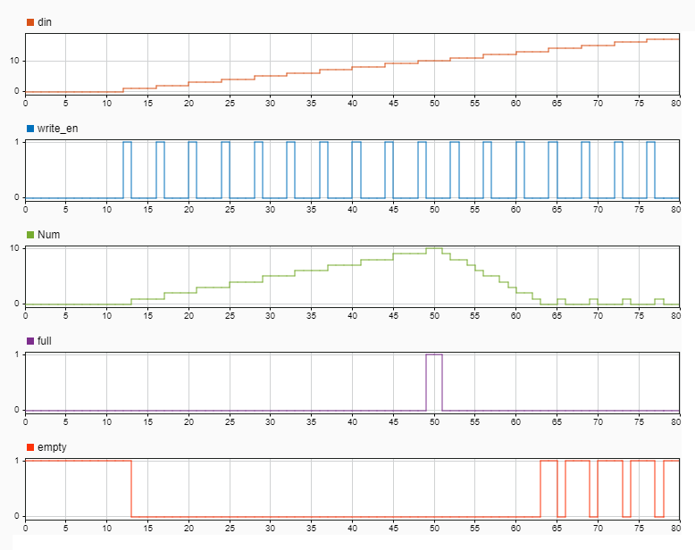
When the write_en signal is 0, the block
does not write data to the FIFO and the empty flag is
asserted.
When the write_en becomes 1, the block
pushes the din signal at input port In to
the end of the FIFO register in the next time step. The Num
signal indicates the number of data entries in the FIFO register. Every time you
write data into the FIFO, the Num signal increments by
1. At time step 12,
write_en is 1. At the next time step
13, data is written to the FIFO. Num
signal increments by 1 and the empty flag is
de-asserted.
This FIFO uses the default register size of 10. When the
Num signal becomes equal to the Register
size at time step 49, the
Full signal is asserted. After the
Full signal becomes 1, if you try to
write more entries into the FIFO, the block generates a warning.
Classic FIFO Read Operation
This figure displays the FIFO read operation. The Pop input port acts as the enable signal for the read operation. This signal is denoted by the read_en signal in the figure.
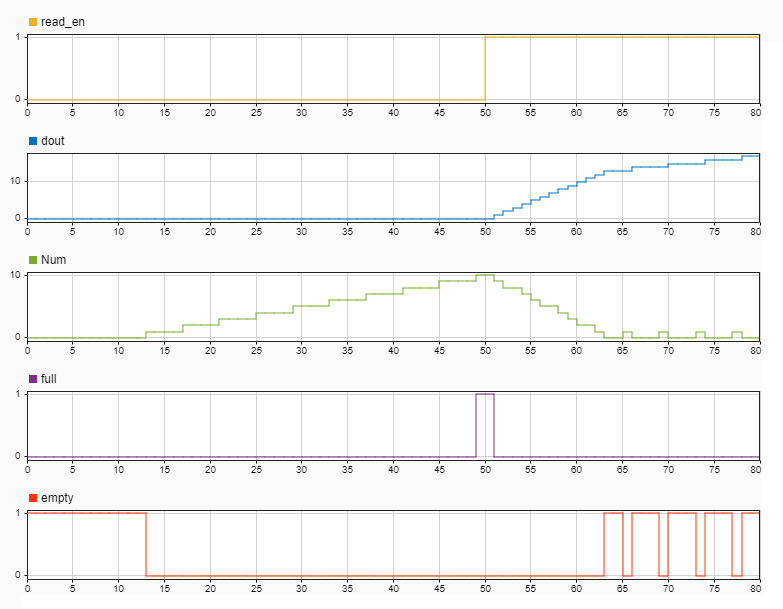
When the read_en signal is 0, the block
output dout is 0. When the
read_en signal becomes 1 at time step
50, the dout signal outputs the oldest
entry in the FIFO in the next time step 51. The
Full flag is de-asserted and the Num
signal decrements by 1 starting from time step
51 as you read data from the FIFO.
When the Num signal becomes equal to 0,
the Empty signal is asserted. After the
Empty signal becomes 0, if you try to
read more entries from the FIFO, the block generates a warning.
FWFT FIFO Read Operation
This figure displays the FIFO read operation. The Pop input port acts as the enable signal for the read operation. This signal is denoted by the read_en signal in the figure.

By default, the HDL FIFO works in the Classic
mode. You can also use a first-word-fall-through (FWFT) mode for the FIFO. In the
Block Parameters dialog box, specify the Mode as
FWFT.
In the FWFT mode, the write operation works in the same way as
the Classic mode. The FWFT mode differs from
the Classic mode when you perform a read operation. In the
Classic mode, after you place a read request or input a
1 to the Pop port, the data becomes
available at the FIFO output in the next clock cycle. In the FWFT
mode, the first word you write to the FIFO falls through to the output and is
available at the output signal Out.
In the figure, though read-en becomes 1 at
time step 50, the FIFO read the first word
dout at time step 15. You can use this
capability to look ahead and see the first word that has been written to the
FIFO.