Test Export-Function Model Simulation Using Schedule Editor
Use the Schedule Editor to schedule the function-call components for simulation. This strategy is useful when you want to set the order of execution for function-call components and view data dependencies between components.
Create a new Simulink® model.
Add a Model block that references the export-function model.
Specify function-call events using the Schedule Editor.
Specify data inputs.
Run a simulation.
To create the model for this example, see Create an Export-Function Model.
To open a completed test model, see ex_export_function_test_model_with_schedule_editor.
Create Test Model (Harness) for Simulation
A Simulink test model is used only for simulation. After simulation testing, generate code from the export-function model, and then manually integrate exported function code with an externally coded scheduler. Referencing an export-function model from a Model block allows the addition of function-call events and logging of data signals for testing without changing the model itself.
Create a new Simulink model.
On the Modeling tab and from the Setup section, select Model Settings
 .
.In the left pane of the Configuration Parameters dialog box, select Solver. In the right pane, select the Solver details arrow to display additional parameters. Select the check boxes for Treat each discrete rate as a separate task and Automatically handle rate transition for data transfer.
Add a Model block to your model
On the Modeling tab, select the Design section, and then select Property Inspector
 .
.In the Model name box, enter
export_function_model. Select the Schedule rates check box. From the Schedule rates drop-down list, selectSchedule Editor.Add Outport blocks to the output_100ms and output_10ms ports on the Model block.
Add a Sine Wave block to provide data input. Set Amplitude to
2and Sample time to0.01. Connect the block to the input_10ms input port on the Model block.
Create Function-Call Events Using the Schedule Editor
Use the Schedule Editor to provide function-call events by defining time-vectors that indicate when events occur for root-level function-call Inport blocks
Open the Schedule Editor. On the Modeling tab and from the Design section, select Schedule Editor
 . The Schedule Editor partitions the function-call
Inport blocks and names the partitions using the block names.
. The Schedule Editor partitions the function-call
Inport blocks and names the partitions using the block names.
Select the function_call_2 partition. In the Hit Times box, enter a matrix with values that begin at 0, periodically increase by 0.01 to 10. You could also test asynchronous behavior by entering a matrix with random values that are multiples of
0.01.
Select the function_call_1 partition. In the Hit Times box, enter a matrix with values that begin at 0, increase by 0.1 to 10.

Simulate Export Function Model
Simulate the export-function model to test and observe its behavior before generating code.
Verify the configuration parameters for Solver Type is set to
Fixed-step, Solver set todiscrete (no continuous states)orauto (Automatic solver selected), and Fixed-step size (fundamental sample time) is set toauto.Set up logging of data signals. Right-click output port signals and select the Log selected signal check box.
On the Simulation tab, select the run button
 .
.Open the Simulation Data Inspector by clicking the toolstrip icon
 .
.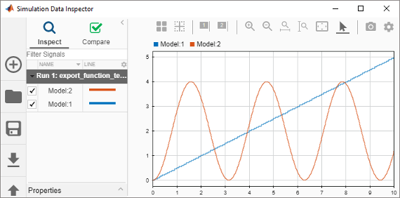
After you test your model, you can generate code for the functions. See Generate Code for Export-Function Model.
See Also
Blocks
Related Topics
- Using the Schedule Editor
- Export-Function Models Overview
- Create an Export-Function Model
- Test Export-Function Model Simulation Using Input Matrix
- Test Export-Function Model Simulation Using Function-Call Generators
- Test Export-Function Model Simulation Using Stateflow Chart
- Generate Code for Export-Function Model