Distributed Pipelining
What Is Distributed Pipelining?
Distributed pipelining, or register retiming, is a speed optimization that moves existing delays in a design to reduce the critical path while preserving functional behavior.
The HDL Coder™ software uses an adaptation of the Leiserson-Saxe retiming algorithm.
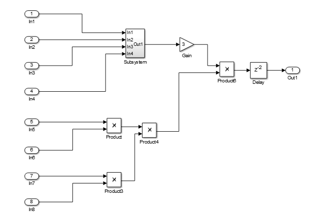
For example, in the following model, there is a delay of 2 at the output.
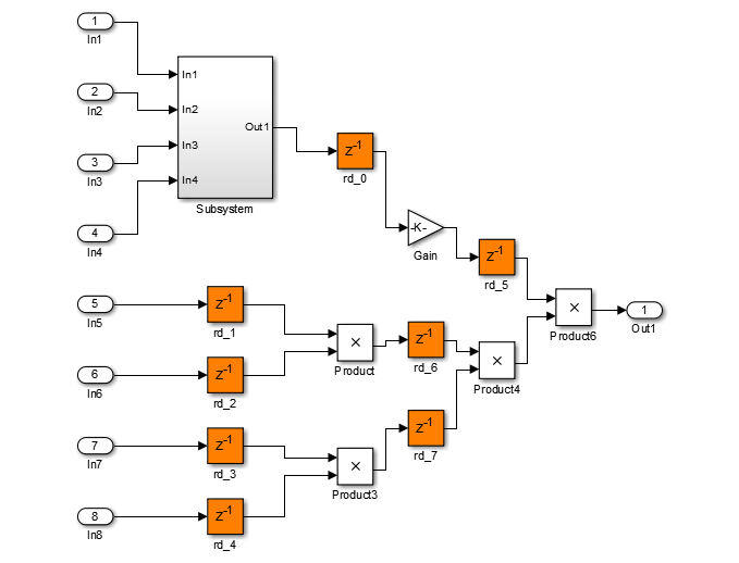
The following diagram shows the generated model after distributed pipelining redistributes the delay to reduce the critical path.
Benefits and Costs of Distributed Pipelining
Distributed pipelining can reduce your design’s critical path, enabling you to use a higher clock rate and increase throughput.
However, distributed pipelining requires your design to contain a number of delays. If you need to insert additional delays in your design to enable distributed pipelining, this increases the area and the initial latency of your design.
Requirements for Distributed Pipelining
Distributed pipelining requires your design to contain delays or registers that can be redistributed. You can use input pipelining or output pipelining to insert more registers.
If your design does not meet your timing requirements at first, try adding more delays or registers to improve your results.
Specify Distributed Pipelining
You can specify distributed pipelining for a subsystem, and Stateflow® charts and MATLAB Function blocks within a subsystem. See Distributed Pipeline Insertion for MATLAB Function Blocks.
To specify distributed pipelining using the UI:
In the Apps tab, select HDL Coder. The HDL Code tab appears. Select the Subsystem and then click HDL Block Properties. Set DistributedPipelining to on and click OK.
Right-click the Subsystem and select HDL Code > HDL Block Properties. Set DistributedPipelining to on and click OK.
To enable distributed pipelining, on the command line, enter:
hdlset_param('path/to/block', 'DistributedPipelining', 'on')
Tip
Output data could be in an invalid state initially if you insert pipeline registers. To avoid test bench errors resulting from initial invalid samples, disable output checking for those samples. For more information, see Ignore output data checking (number of samples).
Limitations of Distributed Pipelining
The distributed pipelining optimization has the following limitations:
Your pipelining results might not be optimal in hardware because the operator latencies in your target hardware may differ from the estimated operator latencies used by the distributed pipelining algorithm.
The HDL Coder software generates pipeline registers at the outputs in the following situations instead of distributing the registers to reduce critical path:
Stateflow chart containing a state, local variable, or a matrix with statically unresolvable index.
HDL Coder distributes pipeline registers around the following blocks instead of within them:
Model
Sum (
Cascadeimplementation)Product (
Cascadeimplementation)MinMax
Upsample
Downsample
Rate Transition
Zero-Order Hold
Reciprocal Sqrt (
RecipSqrtNewtonimplementation)Trigonometric Function (
CORDICApproximation)Single Port RAM
Dual Port RAM
Simple Dual Port RAM
If you enable distributed pipelining for a subsystem that contains these blocks, HDL Coder generates a message during code generation. To fix this message, place these blocks inside one or more subsystems within the original subsystem, and disable hierarchical distributed pipelining. HDL Coder distributes pipeline registers around nested subsystems.
M-PSK Demodulator Baseband
M-PSK Modulator Baseband
QPSK Demodulator Baseband
QPSK Modulator Baseband
BPSK Demodulator Baseband
BPSK Modulator Baseband
PN Sequence Generator
Repeat
HDL Counter
LMS Filter
Sine Wave
Viterbi Decoder
Triggered Subsystem
Counter Limited
Counter Free-Running
Frame Conversion
Distributed Pipelining Report
To see the distributed pipelining information in the report, before you generate code for each subsystem or model reference, enable the optimization report. To enable this report, in the HDL Code tab, select Report Options, and then select Generate optimization report.
When you generate the optimization report, in the Distributed Pipelining section, you see the effect of the distributed pipelining optimization. If distributed pipelining is unsuccessful, the report shows diagnostic messages and offending blocks that caused distributed pipelining to fail.
If distributed pipelining is successful, the report displays comparative listings of registers before and after you apply the distributed pipelining transform.
Selected Bibliography
Leiserson, C.E, and James B. Saxe. “Retiming Synchronous Circuitry.” Algorithmica. Vol. 6, Number 1, 1991, pp. 5-35.