dfilt.wdfallpass
Wave digital allpass filter
Syntax
hd = dfilt.wdfallpass(c)
Description
hd = dfilt.wdfallpass(c) constructs
an allpass wave digital filter structure given the allpass coefficients
in vector c.
Vector c must have, one, two, or four elements
(filter coefficients). Filters with three coefficients are not supported.
When you use c with four coefficients, the first
and third coefficients must be 0.
Given the coefficients in c, the transfer
function for the wave digital allpass filter is defined by
Internally, the allpass coefficients are converted to wave digital
filters for filtering. Note that dfilt.wdfallpass allows
only stable filters. Also note that the leading coefficient in the
denominator, a 1, does not need to be included in vector c.
Use the constructor dfilt.cascadewdfallpass to
cascade wdfallpass filters.
To compare these filters to other similar filters, dfilt.wdfallpass and dfilt.cascadewdfallpass filters
have the same number of multipliers as the non-wave digital filters dfilt.allpass and dfilt.cascadeallpass.
However, the wave digital filters use fewer states and they may require
more adders in the filter structure.
Wave digital filters are usually used to create other filters. This toolbox uses them to implement halfband filters, which the first example in Examples demonstrates. They are most often building blocks for filters.
Properties
In the next table, the row entries are the filter properties and a brief description of each property.
Property Name | Brief Description |
|---|---|
| Contains the coefficients for the allpass wave digital filter object |
| Describes the signal flow for the filter object, including all of the active elements that perform operations during filtering — gains, delays, sums, products, and input/output. |
| Specifies whether to reset the filter states and memory
before each filtering operation. Lets you decide whether your filter
retains states from previous filtering runs. |
| This property contains the filter states before, during,
and after filter operations. States act as filter memory between filtering
runs or sessions. They also provide linkage between the sections of
a multisection filter, such as a cascade filter. For details, refer
to |
Filter Structure
When you change the order of the wave digital filters in the cascade, the filter structure changes as well.
As shown in this example, realizemdl lets
you see the filter structure used for your filter, if you have Simulink® installed.
section11=0.8;
section12=[1.5,0.7];
section13=[1.8,0.9];
hd1=dfilt.cascadewdfallpass(section11,section12,section13);


section21=[0.8,0.4];
section22=[0,1.5,0,0.7];
section23=[0,1.8,0,0.9];
hd2=dfilt.cascadewdfallpass(section21,section22,section23);
% If you have Simulink
realizemdl(hd2)
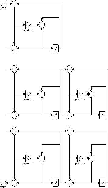
hd1 has this filter structure with three
sections.

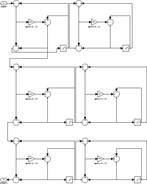
The filter structure for hd2 is somewhat
different, with the different orders and interconnections between
the three sections.

Examples
Construct a second-order wave digital allpass filter with two coefficients. Note that to use
realizemdl, you must have Simulink.
c = [1.5,0.7];
hd = dfilt.wdfallpass(c);
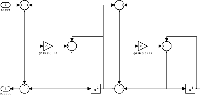
With Simulink installed, realizemdl returns
this structure for hd.

See Also
dfilt | dfilt.allpass | dfilt.cascadeallpass | dfilt.cascadewdfallpass | dfilt.latticeallpass | dsp.CICInterpolator | dsp.IIRHalfbandDecimator