Generate HDL Code for FPGA Floating-Point Target Libraries
Mapping to a floating-point library enables you to synthesize your floating-point design without having to do floating-point to fixed-point conversion. Eliminating the floating-point to fixed-point conversion step reduces the loss of data precision, and enables you to model a wider dynamic range.
An FPGA floating-point library is a set of floating-point IP blocks that are optimized for synthesis on specific target hardware. Altera® Megafunctions and Xilinx® LogiCORE IP are examples of such libraries.
In the HDL Coder™ block library, a subset of Simulink® blocks support floating-point library mapping. See HDL Coder Support for FPGA Floating-Point Library Mapping.
Setup for FPGA Floating-Point Library Mapping
To map your floating-point design to an Altera or Xilinx FPGA floating-point library:
Set the target device options for your Altera or Xilinx FPGA synthesis tool using
hdlset_param. For example, to set the synthesis tool asAltera Quartus IIand chip family asArria10:hdlset_param(model,'SynthesisToolChipFamily','Arria10', ... 'SynthesisToolDeviceName','10AS066H2F34E1SG', ... 'SynthesisToolPackageName','', ... 'SynthesisToolSpeedValue','')
To set up the path to your synthesis tool executable file, use
hdlsetuptoolpath. For example, to set the path to theAltera Quartus IIsynthesis tool:hdlsetuptoolpath('ToolName','Altera Quartus II','ToolPath',... 'C:\altera\14.0\quartus\bin\quartus.exe');
Set up your Altera or Xilinx FPGA floating-point simulation libraries. See FPGA Simulation Library Setup.
Map to an FPGA Floating-Point Library
You can map your Simulink model to floating-point target libraries from the Configuration Parameters dialog box or from the command line.
From the Configuration Parameters Dialog Box
To map to an FPGA floating-point library:
In the Apps tab, select HDL Coder. The HDL Code tab appears. Click Settings.
In the HDL Code Generation > Floating Point Target pane, select the floating-point IP library.
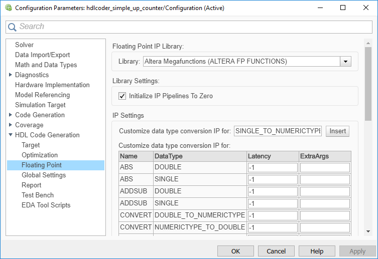
For Xilinx LogiCORE® IP, select XILINX LOGICORE as the library. For Altera megafunction IP, you can select ALTERA MEGAFUNCTION (ALTFP) or ALTERA MEGAFUNCTION (ALTERA FP FUNCTIONS) as the library.
If you choose ALTERA MEGAFUNCTION (ALTERA FP FUNCTIONS) as the library, the Initialize IP Pipelines to Zero option becomes available. Select the Initialize IP Pipelines to Zero option to initialize pipeline registers in the IP to zero. In the Target and Optimizations pane, enter the target frequency that you want the floating-point IP to map to.
Note
When mapping to ALTERA FP FUNCTIONS, the target language must be set to VHDL.
When you choose the
ALTERA FP FUNCTIONSlibrary, an IP Configuration table appears. By using the data type table, you can customize the IP settings of the floating-point target library. For more information, see Customize the IP Latency with Target Frequency.If you choose XILINX LOGICORE or ALTERA MEGAFUNCTION (ALTFP) as the library, select the Latency Strategy and Objective for the IP.
When you choose these libraries, an IP Configuration table appears. By using the data type table, you can customize the latency of the floating-point target IP. For more information, see Customize the IP Latency with Latency Strategy.
To share floating-point IP resources, on the HDL Code Generation > Target and Optimizations > Resource Sharing tab, make sure that Floating-point IPs is enabled. The number of floating-point IP blocks that get shared depends on the SharingFactor that you specify on the subsystem.
Click Apply. On the Simulink Toolstrip, click Generate HDL Code.
From the Command-Line
To generate HDL code from the command line, you can use the
hdlcoder.createFloatingPointTargetConfig function to create a
floating-point IP configuration.
By using the
hdlcoder.createFloatingPointTargetConfigfunction, create ahdlcoder.FloatingPointTargetConfigobject for the floating-point library. Then, usehdlset_paramto save the configuration on the model.For example, to create a floating-point target configuration for the
ALTERA FP FUNCTIONSlibrary with the default settings:fpconfig = hdlcoder.createFloatingPointTargetConfig('ALTERAFPFUNCTIONS'); hdlset_param('sfir_single', 'FloatingPointTargetConfiguration', fpconfig);You can customize the IP settings based on the floating-point library that you specify. For more information, see Customize Floating-Point IP Configuration.
Use
makehdlto generate HDL code from the subsystem.
View Code Generation Reports of Floating-Point Library Mapping
To view the code generation reports of floating-point library mapping, before you begin code generation, enable generation of the Resource Utilization Report and Optimization Report. To learn how to generate these reports, see Create and Use Code Generation Reports.
Target-specific Report
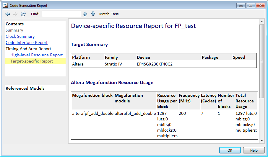
To see the target floating-point block your design mapped to, the latency, and number of target-specific hardware resources, in the Code Generation Report, select Target-specific Report.
Target Code Generation Report
In the Code Generation Report, the Target Code Generation section in the Optimization Report shows the status of optimization settings applied to the model. The report shows whether HDL Coder successfully generated floating-point target code.

Analyze Results of Floating-Point Library Mapping
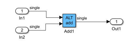
You can get the latency information of the floating-point target IP from the generated model after HDL code generation. For example, consider this add block in Simulink with inputs of double data type.

After HDL code generation, the optimization report for target code generation displays a link to a generated model. To see the floating-point target library that your Simulink block mapped to, double-click the subsystem in the generated model.
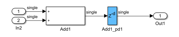
Double-click the ALT add block. The length of the delay block is the latency of the floating-point target IP.
To learn more about the generated model, see Generated Model and Validation Model.
To see your FPGA floating-point library mapping results, you can view the IP core files generated after HDL code generation.

HDL Coder checks and reuses existing generated IP core files, taking less time when successively generating code for the same floating-point target IP.