Matrix Viewer
Display matrices as color images
Library
Sinks
dspsnks4

Description
The Matrix Viewer block displays an M-by-N matrix input by mapping the matrix element values to a specified range of colors. The display is updated as each new input is received. This block treats an unoriented length M vector input as an M-by-1 matrix.
You can use the Matrix Viewer block in models running in Normal or Accelerator simulation modes. The software does not support this block in models running in Rapid Accelerator or External mode. For more information about these modes, see How Acceleration Modes Work (Simulink) in the Simulink® User's Guide.
Image Properties
Select the Image Properties tab to show the image property parameters, which control the colormap and display.
You specify the mapping of matrix element values to colors in the Colormap matrix, Minimum input value, and Maximum input value parameters. For a colormap with L colors, the colormap matrix has dimension L-by-3, with one row for each color and one column for each element of the RGB triple that defines the color. Examples of RGB triples are
[ 1   0   0 ]   (red)
[ 0   0   1 ]   (blue)
[0.8 0.8 0.8]   (light gray)
See the ColorSpec property in the
MATLAB® documentation for complete information about defining RGB
triples.
MATLAB provides a number of functions for generating predefined colormaps,
such as hot, cool,
bone, and autumn. Each of
these functions accepts the colormap size as an argument, and can be used in the
Colormap matrix parameter. For example, when you specify
gray(128) for the Colormap matrix
parameter, the matrix is displayed in 128 shades of gray. The color in the first row
of the colormap matrix represents the value specified by the Minimum input
value parameter, and the color in the last row represents the value
specified by the Maximum input value parameter. Values between
the minimum and maximum are quantized and mapped to the intermediate rows of the
colormap matrix.
The documentation for the MATLAB
colormap function provides complete
information about specifying colormap matrices, and includes a complete list of the
available colormap functions.
Axis Properties
Select the Axis Properties tab to show the axis property parameters, which control labeling and positioning.
The Axis origin parameter determines where the first element
of the input matrix, U(1,1), is displayed. When you specify
Upper left corner, the matrix is displayed in matrix
orientation, with U(1,1) in the upper-left corner.
When you specify Lower left corner, the matrix is
flipped vertically to image orientation, with U(1,1) in the
lower-left corner.
Axis zoom, when selected, causes the image display to completely fill the figure window. Axis titles are not displayed. This option can also be selected from the pop-up menu that is displayed when you right-click in the figure window. When Axis zoom is cleared, the axis labels and titles are displayed in a gray border surrounding the image axes.
To customize the axis tick range, set Axis tick mode to
User-defined and specify a two-element row vector,
[Minvalue Maxvalue], in X-tick range and
Y-tick range. The matrix data does not change even when the
axes ticks change. For example, consider displaying a matrix on axes with ticks
ranging from 0 to 10. When you set X-tick range and
Y-tick range to [0 1], the range of ticks changes from [0
10] to [0 1].
Figure Window
The image title in the figure title bar is the same as the block title. The axis tick marks reflect the size of the input matrix; the x-axis is numbered from 1 to N (number of columns), and the y-axis is numbered from 1 to M (number of rows).
Right-click the image in the figure window to access the following menu items:
Refresh erases all data on the scope display except for the most recent image.
Autoscale recomputes the minimum and maximum input values to fit the range of values observed in a series of 10 consecutive inputs. The numerical limits selected by the autoscale feature are shown in the Minimum input value and Maximum input value parameters, where you can make further adjustments to them manually.
Axis zoom, when selected, causes the image to completely fill the figure window. Axis titles are not displayed. When Axis zoom is cleared, the axis labels and titles are displayed in a gray border surrounding the scope axes. This option can also be set in the Axis Properties pane of the parameter dialog box.
Colorbar, when selected, displays a bar with the specified colormap to the right of the image axes.
Save Position automatically updates the Figure position parameter in the Axis Properties pane to reflect the figure window's current position and size on the screen. To make the scope window open at a particular location on the screen when the simulation runs, drag the window to the desired location, resize it, and select Save Position. The parameter dialog box must be closed when you select Save Position for the Figure position parameter to be updated.
Dialog Box
The Image Properties pane of the Matrix Viewer block appears as follows.
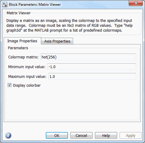
- Colormap matrix
A 3-column matrix defining the colormap as a set of RGB triples, or a call to a colormap-generating function such as
hotorspring. See theColorSpecproperty for complete information about defining RGB triples, and the MATLABcolormapfunction for a list of colormap-generating functions. Tunable (Simulink).- Minimum input value
The input value to be mapped to the color defined in the first row of the colormap matrix. Right-click in the figure window and select
Autoscalefrom pop-up menu to set this parameter to the minimum value observed in a series of 10 consecutive matrix inputs. Tunable (Simulink).- Maximum input value
The input value to be mapped to the color defined in the last row of the colormap matrix. Right-click in the figure window and select
Autoscalefrom the pop-up menu to set this parameter to the maximum value observed in a series of 10 consecutive matrix inputs. Tunable (Simulink).- Display colorbar
Select to display a bar with the selected colormap to the right of the image axes. Tunable (Simulink).
The Axis Properties pane of the Matrix Viewer block appears as follows.

- Axis origin
The position within the axes where the first element of the input matrix, U(1,1), is plotted; bottom left or top left. Tunable (Simulink).
- Axis tick mode
The mode used to specify the axis tick range. When you select
Auto, the x-axis tick range and y-axis tick range are chosen based on the input signal. When you selectUser-defined, the axis tick range is set based on the values you specify in X-tick range and Y-tick range. The default isAuto.- X-tick range
x-axis tick range, specified as a two-element row vector of real scalars, [Xmin Xmax]. This parameter applies only when you set Axis tick mode to
User-defined. When you change X-tick range during simulation, the axis range on the Matrix Viewer block updates in real time. The default is [0 1].- Y-tick range
y-axis tick range, specified as a two-element row vector of real scalars, [Ymin Ymax]. This parameter applies only when you set Axis tick mode to
User-defined. When you change Y-tick range during simulation, the axis range on the Matrix Viewer block updates in real time. The default is [0 1].- X-axis title
The text to be displayed below the x-axis. Tunable (Simulink).
- Y-axis title
The text to be displayed to the left of the y-axis. Tunable (Simulink).
- Colorbar title
The text to be displayed to the right of the color bar, when Display colorbar is currently selected. Tunable (Simulink).
- Figure position, [x y width height]
A 4-element vector of the form
[x y width height]specifying the position of the figure window, where(0,0)is the lower-left corner of the display. Tunable (Simulink).- Axis zoom
Resizes the image to fill the figure window. Tunable (Simulink).
Supported Data Types
| Port | Supported Data Types |
|---|---|
Input |
|