HDL Minimum Resource FFT (Obsolete)
FFT— optimized for HDL code generation using minimum hardware resources
Library
Obsolete
dspobs

Description
Note
The HDL Minimum Resource FFT block will be deprecated in a future release. Use the
Burst Radix 2 architecture of the FFT HDL Optimized block instead.
The HDL Minimum Resource FFT block implements an FFT architecture that uses minimal hardware resources. The HDL Minimum Resource FFT block supports the Radix-2 with decimation-in-time (DIT) algorithm for FFT computation. See the FFT block for more information about this algorithm.
The results returned by the HDL Minimum Resource FFT block are bit-for-bit compatible with results returned by the FFT block. The operation of the HDL Minimum Resource FFT block differs from the FFT block, due to the requirements of hardware realization. The HDL Minimum Resource FFT block:
Requires serial input
Generates serial output
Operates in burst I/O mode
The HDL Minimum Resource FFT block provides handshaking signals to support these features.
Block Inputs and Outputs
As shown in the following figure, the HDL Minimum Resource FFT block has two input ports and three output ports. Two of these ports are for data input and output signals. The other ports are for control signals.
The input ports are:
din: The input data signal. A complex signal is required.start: Boolean control signal. When this signal is asserted true (1), the HDL Minimum Resource FFT block initiates processing of a data frame.
The output ports are:
dout: Data output signal. The Radix-2 with DIT algorithm produces output with linear ordering.dvalid: Boolean control signal. The HDL Minimum Resource FFT block asserts this signal true (1) when a burst of valid output data is available at thedoutport.ready: Boolean control signal. The HDL Minimum Resource FFT block asserts this signal true (1) to indicate that it is ready to process a new frame.
Configuring Control Signals
For efficient hardware deployment of the HDL Minimum Resource FFT block, the
timing of the block's input and output data streams must be considered
carefully. The following figure shows the timing relationships between the
system clock and the start, ready, and
dvalid signals.
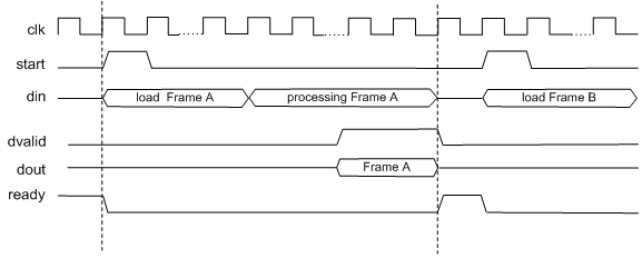
When ready is asserted, the start signal
(active high) triggers the block. The high cycle period of the
start signal does not
affect the behavior of the block.
One clock cycle after the start trigger, the block begins
to load data and the ready signal is deasserted. During the
interval when the block is loading, processing, and outputting data,
ready is low and the start signal is
ignored.
The dvalid signal is asserted high for N clock cycles
(where N is the FFT length) after processing is complete.
ready is asserted again after the N-point FFT outputs are
sent out.
The expression Tcycle denotes the total number of clock
cycles required by the HDL Minimum Resource FFT block to complete an FFT of
length N. Tcycle is defined as follows:
Where N >8
Tcycle = 3N/2-2 + log2(N)*(N/2+3);
Where N = 8
Tcycle = 3N/2-1 +log2(N)*(N/2+3);
Given Tcycle, you can then define the period between
assertions of the HDL Minimum Resource FFT start signal in a
way that is suitable to your application. In the “Using the Minimum
Resource HDL FFT” example, this period is computed and assigned to the
variable startLen, as follows:
if (N<=8)
startLen = (ceil(Tcycle/N)+1)*N;
else
startLen = ceil(Tcycle/N)*N;
end
In the example model, startLen determines the period of a
Pulse Generator that drives the HDL Minimum Resource FFT block's
start input. These values are computed in the model's
initialization function (InitFcn), which is defined in the
Callbacks pane of the Simulink® Model Explorer.
The HDL Minimum Resource FFT block asserts and deasserts the
ready and dvalid signals
automatically. These signals are routed to the model components that write to
and read from the HDL Minimum Resource FFT block.
Parameters
FFT Length
Default: 8
The FFT length must be a power of 2, in the range 23 .. 216.
Rounding mode
Default: Floor
The HDL Minimum Resource FFT block supports all rounding modes of the FFT block. See also the FFT block reference section.
Overflow mode
Default: Saturate
The HDL Minimum Resource FFT block supports all overflow modes of the FFT block. See also the FFT block reference section.
Sine table
Default: Same word length as input
Choose how you specify the word length of the values of the sine table. The fraction length of the sine table values is equal to the word length minus one.
When you select
Same word length as input, the word length of the sine table values match that of the input to the block.When you select
Specify word length, you can enter the word length of the sine table values, in bits, in the Sine table word length field. The sine table values do not obey the Rounding mode and Overflow mode parameters; they always saturate and round toNearest.
Product output
Default: Same as input
Use this parameter to specify how you want to designate the product output word and fraction lengths:
When you select
Same as input, these characteristics match those of the input to the block.When you select
Binary point scaling, you can enter the word length and the fraction length of the product output, in bits, in the Product word length and Product fraction length fields.
Accumulator
Default: Same as input
Use this parameter to specify how you want to designate the accumulator word and fraction lengths:
When you select Same as product output, these
characteristics match those of the product output.
When you select
Same as input, these characteristics match those of the input to the block.When you select
Binary point scaling, you can enter the word length and the fraction length of the accumulator, in bits, in the Accumulator word length and Accumulator fraction length fields.
Output
Default: Same as input
Choose how you specify the output word length and fraction length:
When you select
Same as input, these characteristics match those of the input to the block.When you select
Binary point scaling, you can enter the word length and the fraction length of the output, in bits, in the Output word length and Output fraction length fields.
Note
The HDL FFT block skips the divide-by-two operation on butterfly outputs for fixed-point signals.
Signal Processing with the HDL FFT Block
To get started with the HDL Minimum Resource FFT block, run the “Using the Minimum Resource HDL FFT” example, which is located in the HDL Coder™/Signal Processing example library.
The example illustrates the use of the HDL Minimum Resource FFT block in simulation. The model includes buffering and control logic that handles serial input and output. In the example, a complex source signal is stored as a series of samples in a FIFO. Samples from the FIFO are processed serially by the HDL Minimum Resource FFT block, which emits a stream of scalar FFT data.
For comparison, the same source signal is also processed by the frame-based FFT block. The output frames from the FFT block are buffered into a FIFO and compared to the output of the HDL Minimum Resource FFT block. Examination of the results shows the outputs to be identical.
HDL Code Generation
HDL Coder provides additional configuration options that affect HDL implementation and synthesized logic.
HDL Architecture
This block has a single, default HDL architecture.
HDL Block Properties
| ConstrainedOutputPipeline | Number of registers to place at
the outputs by moving existing delays within your design. Distributed
pipelining does not redistribute these registers. The default is
|
| InputPipeline | Number of input pipeline stages
to insert in the generated code. Distributed pipelining and constrained
output pipelining can move these registers. The default is
|
| OutputPipeline | Number of output pipeline stages
to insert in the generated code. Distributed pipelining and constrained
output pipelining can move these registers. The default is
|